Tutorial Module11 Archive
Introduction
This page introduces a basic dam break model setup, and will discuss the following topics:
- Setting initial water level inside a dam
- Changing 2D cell elevations to trigger dam break
- Modelling output and
- Model updates to use TUFLOW HPC
In this module we will further develop the model from Module 01. Please download the tutorial dataset matching your preferred GIS package from the TUFLOW website and complete Module 01 before attempting this tutorial, it is the starting point for the model updates documented below.

UK EA Test Case 6
Note: Superseded version of this tutorial is located here.
Module Data
New GIS datasets have been provided in the Module_Data\Module_11 folder.
MapInfo Users:
- 2d_iwl_M11_001.TAB
- 2d_vzsh_M11_dambreak_001.TAB
- 2d_zsh_M11_damwall_001.TAB
Save these files to your gis working directory (TUFLOW/Model/mi).
ArcGIS or QGIS Users:
- 2d_iwl_M11_001_R.shp
- 2d_vzsh_M11_dambreak_001_P.shp
- 2d_vzsh_M11_dambreak_001_R.shp
- 2d_zsh_M11_damwall_001_L.shp
Save these files to your gis working directory (TUFLOW/Model/gis).
Model Update
Update Boundary Condition
In this dam break model, we only need to keep the downstream HQ boundary. To update the boundary conditions:
- Save the TUFLOW Control File (TCF) (M01_5m_002.tcf) as M11_5m_001.tcf.
- Save the TUFLOW Boundary Control File (TBC) (M01_5m_002.tbc) as M11_5m_001.tbc, and update the following lines with the file.
- Comment out (!) or delete the line 'Read GIS SA == ...'. This will remove the eastern upstream SA inflow boundary.
MapInfo Users:
- Open 2d_bc_M01_002.tab. Save the file as 2d_bc_M11_001.tab and delete the southwest (upstream) QT boundary. Save and export the updated file to mif/mid format.
- Update the Read GIS BC command in the TBC file (M11_5m_001.tbc).
- Read GIS BC == mi\2d_bc_M11_001.mif
- Save the TBC file (M11_5m_001.tbc).
- Open 2d_bc_M01_002_L.shp. Save the file as 2d_bc_M11_001_L.shp and delete the southwest (upstream) QT boundary. Save the updated file.
- Update the Read GIS BC command in TBC file (M11_5m_001.tbc).
- Read GIS BC == gis\2d_bc_M11_001_L.shp
- Save the TBC file (M11_5m_001.tbc).
- Update the TBC file reference in the TCF file (M11_5m_001.tcf).
BC Control File == ..\model\M11_5m_001.tbc - Save the TCF file (M11_5m_001.tcf).
Update Geometry
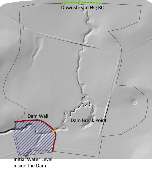
We will add a breakline to the model along the south western road as a representative demonstration of a dam wall.

- Save the TUFLOW Geometry Control (TGC) file (M01_5m_002.tgc) as M11_5m_001.tgc.
MapInfo Users:
- Open the 2d_zsh_M11_damwall_001.tab file from your gis working directory (TUFLOW/Model/mi).
. In this tutorial a damwall is represented by a breakline along the south west road crest. The attributes were set as following:
- Z = 60
- Shape_Width_or_dMax = 5
- Note: Given the model grid size is 5m, this addition to the model creates a "THICK" breakline with a constant elevation of 60m.
- Save and export the file to mif/mid format.
- Update the TGC file (M11_5m_001.tgc) file by adding the following command at the bottom of the file:
- Read GIS Z Shape == mi\2d_zsh_M11_damwall_001.mif
- Save the TGC file.
- Open the 2d_zsh_M11_damwall_001_L.shp file from your gis working directory (TUFLOW/Model/gis). In this tutorial a damwall is represented by a breakline along the south west road crest. The attributes were set as following:
- Z = 60
- Shape_Width_or_dMax = 5
- Note: Given the model grid size is 5m, this addition to the model creates a "THICK" breakline with a constant elevation of 60m.
- Update the TGC file (M11_5m_001.tgc) file by adding the following command at the bottom of the file:
- Read GIS Z Shape == gis\2d_zsh_M11_damwall_001_L.shp
- Save the TGC file.
- Open the 2d_zsh_M11_damwall_001.tab file from your gis working directory (TUFLOW/Model/mi).
- Update the TGC file reference in the TCF file (M11_5m_001.tcf).
Geometry Control File == ..\model\M11_5m_001.tgc - Save the TCF file (M11_5m_001.tcf).
Note: This Tutorial focuses on demonstration of dam wall failure within a model. It is acknowledged that in this 2D example the dam extent abuts the model code polygon. As such, the total volume of water associated with the dam is underestimated. It is important that the entire dam volume is represented in real world assessments. This can be done by capturing the whole dam extent in 2D or via 1D nodal (storage) area table inputs using a 1D or linked 1D/2D configurations.
Set Initial Water Level
Now we will set the initial water level inside the dam.

MapInfo Users:
- Open the 2d_iwl_empty layer from the '\empty' folder and save it as 2d_iwl_M11_001.tab in the 'Model/mi' folder. Draw a polygon inside the dam. Make sure the polygon vertexes are snapped to the dam wall breakline and the polygon covers all the active domain upstream the dam wall.
- Set the "IWL" attribute as 60.
- Save and export the initial water level file to mif/mid format.
- Open TCF file (M11_5m_001.tcf) and add the following command below the existing Set IWL == 36 command.
- Read GIS IWL == ..\model\mi\2d_iwl_M11_001.mif
- Save the TCF file (M11_5m_001.tcf).
ArcGIS or QGIS Users:
- Open the 2d_iwl_empty_R layer from the '\empty' folder and save it as 2d_iwl_M11_001_R.shp in the 'Model/gis' folder. Draw a polygon inside the dam. Make sure the polygon vertexes are snapped to the dam wall breakline and the polygon covers all the active domain upstream the dam wall.
- Set the "IWL" attribute as 60.
- Save the initial water level file.
- Open TCF file (M11_5m_001.tcf) and add the following command below the existing Set IWL == 36 command.
- Read GIS IWL == ..\model\gis\2d_iwl_M11_001_R.shp
- Save the TCF file (M11_5m_001.tcf).
Set Variable Bed Elevation
In this section, we will add a Variable Z Shape Layer (2d_vzsh) to trigger the dam breach. A 2d_vzsh layer is used to define the final topographic shape at the end of the breach. Attributes associated with the feature are used to define the trigger mechanism and also the duration over which the breach occurs.
MapInfo Users:
- Open the 2d_vzsh_M11_dambreak_001.tab file from your gis working directory (TUFLOW/Model/mi).
ArcGIS or QGIS Users:
- Open the 2d_vzsh_M11_dambreak_001_R.shp and 2d_vzsh_M11_dambreak_001_P.shp files from your gis working directory (TUFLOW/Model/gis).

- Digitised polygon shown at the image above simulates the location of embankment breach. The polygon has defined eight vertices. TUFLOW will create a TIN based on the model elevations around the polygon perimeter at 1/2 cell increments (in doing so, breaching the dam wall). We have placed two corner vertices each along the upstream and downstream faces of the polygon. Each side of the polygon that passes through the dam wall includes two additional vertices which will be used in combination with point features (discussed in the following bullet point). Note the following attributes for the polygon:
- Trigger_Value = 1.0
- Period = 0.1
- Points are snapped to the polygon vertices on either side of the dam wall. The Z attribute is set value to -99999. This value and the point placement on neighbouring polygon vertices has a special purpose for 2d_vzsh and 2d_zsh topographic inputs. As mentioned above, the polygon will create a TIN based on the model elevations around the polygon perimeter. Points with an elevation value of -99999 and snapped to neighbouring polygon vertices will exclude the intermediate segment of the polygon from the perimeter TIN. As such, the section highlighted in pink in the above figure will be ignored from the post-breached geometry TIN.
- Open the TGC file (M11_5m_001.tgc).
- MapInfo Users:
- Add the following command below Read GIS Z Shape == mi\2d_zsh_M11_damwall_001.mif
- Read GIS Variable Z Shape == mi\2d_vzsh_M11_dambreak_001.mif
- ArcGIS or QGIS Users:
- Add the following command below Read GIS Z Shape == gis\2d_zsh_M11_damwall_001_L.shp
- Read GIS Variable Z Shape == gis\2d_vzsh_M11_dambreak_001_R.shp | gis\2d_vzsh_M11_dambreak_001_P.shp
- MapInfo Users:
- Save and close the TGC file (M11_5m_001.tgc).
After completing all of the updates above your model should now look like this:

Update the TUFLOW Control File (TCF) and Run The Simulation
- Open the TCF File (M11_5m_001.tcf)
- Add "ZH" in the "Map Output Data Types" to output the bed elevation. This will let you view how the model elevation has changed over time, so you can confirm the model breach is behaving appropriately. the output command should now look like:
Map Output Data Types == h V d ZH
- Update the output folder location:
Output Folder == ..\results\M11\2d
- Run the TCF (M11_5m_001.tcf) using your preferred method.
Please refer to Module 1 for a detailed description of the various methods for running a TUFLOW simulation.
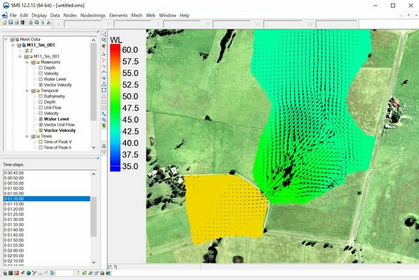
Results Review
- Check the map outputs for water level, flow velocity and bathymetry. How does the water level and the flow velocity develop during the dam break? How does the bed elevation change over time?
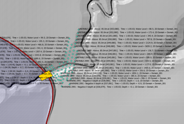
- Review the TUFLOW log File (M11_5m_001.tlf).
You should find the model produced numerous warning messages (over 250) and an unacceptable mass error for a TUFLOW Classic model (>1%).
- Reduce the model timestep to 0.5s and run the model using the double precision version of TUFLOW. These changes should have fixed the above mentioned warning messages and mass error. The warning message log should have been reduced to less than 10 items. Also, the mass error should have reduced from 5% to an acceptable value of 0.3% (less than the target 1%).


Dam break hydraulics are highly transient (exhibiting high velocity and water level gradients that can change dramatically in time and space). Dam break modelling completed using TUFLOW Classic typically requires the double precision version of TUFLOW and smaller timesteps than what is considered 'normal' for catchment flood modelling because of the transient nature of dam break flows.
TUFLOW HPC
TUFLOW HPC was released in September 2017. It is an explicit solver for the full 2D Shallow Water Equations (SWE), including a sub-grid scale eddy viscosity model. The scheme is both volume and momentum conserving, is 2nd order in space and 4th order in time. It uses a variety of control number stability criteria in an automated adaptive timestep framework to achieve unconditional stability (TUFLOW Classic doesn't include this feature). Over 12 months of development was dedicated to modelling accuracy and simulation speed for dam break assessments prior to its release and use on the 2017-2018 United Kingdom Reservoir Flood Inundation Study project (an assessment of the flood risk associated with all registered reservoirs in the United Kingdom - over 2000 in total). The speed and stability of TUFLOW HPC make it particularly well suited to dam break simulations. As such, even though TUFLOW Classic can be used in its own right, TUFLOW HPC is the recommended solver for dam break modelling.
Please refer to the TUFLOW Manual or HPC Modelling Guidance page of the Wiki for more details.
Perform the following steps to use the TUFLOW HPC solver instead of TUFLOW Classic:
- Open the TUFLOW Control File (TCF) (M11_5m_001.tcf) and save a copy of the file as M11_5m_002.tcf.
- Add the following command to the TCF file:
- Solution Scheme == HPC ! Use HPC solver to run the model
- Solution Scheme == HPC ! Use HPC solver to run the model
- If you have a CUDA enabled NVIDIA GPU device, you can also add the following command to run the HPC solver using GPU hardware:
- Hardware == GPU ! Run HPC solver on GPU
- Hardware == GPU ! Run HPC solver on GPU
- Save the TCF file.
- Run the model using the single precision version of TUFLOW.
Conclusion
This tutorial provided an example of dam break modelling.
- The simulation demonstrated how the transient nature of dam break flows typically require TUFLOW Classic simulations to use a reduced timestep and the double precision executable to remain stable.
- TUFLOW HPC is the recommended solver for dam break modelling (instead of TUFLOW Classic). This is due to its unconditional stability and explicit mass conserving solution design.
The greatest uncertainty associated with dam break modelling is the mechanism of dam wall failure. The failure characteristics determine the shape and duration of the flood hydrograph originating from the upstream reservoir. Numerous options are possible:
- This tutorial provided an example of dam break modelling using a simple '2d_vzsh' layer. More complex failure triggers and breach geometries can be modelled using '2d_vzsh' layers.
- External models or analytical methods can be used to derive a breach hydrograph that is applied to the base of the dam wall (i.e. the reservoir is not modelled explicitly in the hydraulic model). This approach is modelled using a 2d_sa inflow polygon as the inflow location at the base of the dam wall. The polygon size should have a width matching the physical breach extent. The breath should cover 2-10 cells in the downstream direction depending on the flow magnitude and cell size.
