Difference between revisions of "QGIS Create a TIN"
| Line 79: | Line 79: | ||
<li>The resulting layer, called '''Draped''' will appear in the QGIS Layers panel. Right click '''Draped''' and select 'Rename Layer'. Rename the layer to '''Draped_Lines'''. | <li>The resulting layer, called '''Draped''' will appear in the QGIS Layers panel. Right click '''Draped''' and select 'Rename Layer'. Rename the layer to '''Draped_Lines'''. | ||
</ol> | </ol> | ||
| + | |||
| + | ==Create TIN Mesh== | ||
| + | Create a TIN Mesh using the QGIS processing tool 'TIN Mesh Creation'. This tool will generate a TIN mesh from the above outputs and any elevation points that are not snapped to the merge polygon. For more information about this tool, please refer to <u>[https://docs.qgis.org/3.34/en/docs/user_manual/processing_algs/qgis/mesh.html#tin-mesh-creation QGIS Documentation - TIN Mesh Creation]</u>. | ||
| + | <ol> | ||
| + | <li>Go to 'Mesh' in the processing tool list and select 'TIN Mesh Creation'. This opens the dialog shown below: | ||
| + | *Vector Layer: '''Draped_Lines''' | ||
| + | *Value on Vertex: Leave as default and tick on 'Use Z-coordinate for Value on Vertex'. | ||
| + | *Click [[File: QGIS_3D_Animation_add_keyframe_button_01.png|30px]] to add the vector layer to the table. Repeat the above two points for '''Draped_Polygon'''. | ||
| + | :*If there are any points layers within the merge polygon's extent but not snapped to the polygon, add these as well. For 'Value on Vertex', select the field that contains the elevation data (e.g. '''Z'''). | ||
| + | *Output format: 2DM | ||
| + | *Output coordinate system: Use the project CRS. | ||
| + | *Output file: Save to the model's '''grid''' folder ('''TUFLOW\model\grid'''). | ||
| + | <li>Click 'Run'. Once the tool is finished, click 'Close'. <br> | ||
| + | <br> | ||
| + | [[File: QGIS_Create_TIN_Create_Mesh_01a.png]]<br> | ||
| + | <br> | ||
| + | <li>The resulting layer will appear in the QGIS Layers panel. | ||
| + | <li>To view the triangular mesh, right click the TIN Mesh and select 'Properties'. | ||
| + | <li>In the 'Symbology' tab, select 'Rendering' from the top options and tick on 'Triangular Mesh Rendering'. Click 'OK'. <br> | ||
| + | <br> | ||
| + | [[File:QGIS_Create_TIN_Create_Mesh_02.png]]<br> | ||
| + | <br> | ||
| + | </ol> | ||
| + | |||
| + | ==Update TUFLOW Geometry Control File (TGC)== | ||
| + | The TUFLOW Geometry Control File (.tgc) must be updated to reference the TIN Mesh, which will replace any topography-modifying GIS layers (Z shapes) within the mesh extent. | ||
| + | |||
| + | Remove all references to Z shapes (<tt><font color="blue">Read GIS Z Shape</font><font color="red"> ==</font></tt> ) in the TGC file and replace them with:<br> | ||
| + | <tt><font color="blue">Read TIN Zpts</font><font color="red"> ==</font> grid\<TIN_Mesh_filename>.2dm | gis\<merge_polygon_filename></tt> | ||
| + | |||
| + | For example: | ||
| + | |||
| + | |||
=Conclusion= | =Conclusion= | ||
Revision as of 11:05, 30 January 2025
Page Under Construction
Introduction
Method
This example uses the DEM and GIS files from Tutorial Module 2 (part 2).
Densify Merge Polygon Vertices
Densify the merge polygon vertices using the QGIS processing tool 'Densify by Interval'. For more information about this tool, please refer to the QGIS Documentation - Densify by Interval.
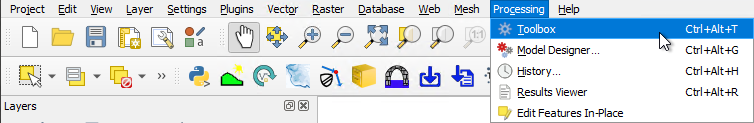
- In QGIS, go to Processing > Toolbox from the top dropdown menu options to open the Processing Toolbox.
- Go to 'Vector geometry' in the processing tool list and select 'Densify by interval'. This opens the dialog shown below:
- Input layer: Select the merge polygon (e.g. 2d_zsh_M02_landscape_002_R).
- Interval between vertices to add: This value should set to the smaller of the following two values - half the model cell size, or the finest quadtree level.
- Densified: Leave as default.
- Tick on 'Open output file after running algorithm'.
- Click 'Run'. Once the tool is finished, click 'Close'.

- The resulting layer, called Densified will appear in the QGIS Layers panel. This is a copy of the merge polygon, now updated with additional vertices based on the specified interval.
- In the QGIS Layers panel, right click Densified and select 'Rename Layer'. Rename the layer to Densified_Polygon.
Note: To see the vertices, toggle on editing for Densified_Polygon and select the 'Vertex Tool' from the Digitizing toolbar. Hover over the polygon to see the vertices.


Extract Elevation of Polygon Vertices from DEM
Extract elevation at polygon vertices from DEM using the QGIS processing tool 'Drape (set Z value from raster)'. For more information about this tool, please refer to QGIS Documentation - Drape.
- Go to 'Vector geometry' in the processing tool list and select 'Drape (set Z value from raster)'. This opens the dialog shown below:
- Input layer: Densified_Polygon
- Raster layer: Select the DEM file.
- Leave all other options as default and ensure 'Open output file after running algorithm' is ticked on.
- Click 'Run'. Once the tool is finished, click 'Close'.

- The resulting layer, called Draped will appear in the QGIS Layers panel. Right click Draped and select 'Rename Layer'. Rename the layer to Draped_Polygon.

Generate IDW Interpolation
Generate a IDW (Inverse Distance Weighted) interpolation of the z shape points layer, using the QGIS processing tool 'IDW Interpolation'. For more information about this tool, please refer to QGIS Documentation - IDW Interpolation.
- Go to 'Interpolation' in the processing tool list and select 'IDW Interpolation'. This opens the dialog shown below:
- Vector layer: Select the z shape points layer (e.g. 2d_zsh_M02_landscape_002_P).
- Interpolation attribute: Select Z. This is the attribute that contains elevation data.
- Click
 to add the vector layer to the table. Repeat the above two points for all points layers within the merge polygon extent.
 - Distance coefficient P: Leave as default.
- Extent: Click
 and select 'Calculate from Layer' >> 'Draped_Polygon'.
 - Interpolated: Leave as default.
- Tick on 'Open output file after running algorithm'.
- Click 'Run'. Once the tool is finished, click 'Close'.

- The resulting file, called Interpolated will appear in the QGIS Layers panel.


Extract Elevation of Breakline Vertices From IDW Interpolation
Extract elevation at breakline vertices from Interpolated using the QGIS processing tool 'Drape (set Z value from raster)'. For more information about this tool, please refer to QGIS Documentation - Drape.
- Go to 'Vector geometry' in the processing tool list and select 'Drape (set Z value from raster)'. This opens the dialog shown below:
- Input layer: Select the breaklines layer (e.g. 2d_zsh_M02_landscape_002_L).
- Raster layer: Interpolated
- Leave all other options as default and ensure 'Open output file after running algorithm' is ticked on.
- Click 'Run'. Once the tool is finished, click 'Close'.

- The resulting layer, called Draped will appear in the QGIS Layers panel. Right click Draped and select 'Rename Layer'. Rename the layer to Draped_Lines.

Create TIN Mesh
Create a TIN Mesh using the QGIS processing tool 'TIN Mesh Creation'. This tool will generate a TIN mesh from the above outputs and any elevation points that are not snapped to the merge polygon. For more information about this tool, please refer to QGIS Documentation - TIN Mesh Creation.
- Go to 'Mesh' in the processing tool list and select 'TIN Mesh Creation'. This opens the dialog shown below:
- Vector Layer: Draped_Lines
- Value on Vertex: Leave as default and tick on 'Use Z-coordinate for Value on Vertex'.
- Click to add the vector layer to the table. Repeat the above two points for Draped_Polygon.
- If there are any points layers within the merge polygon's extent but not snapped to the polygon, add these as well. For 'Value on Vertex', select the field that contains the elevation data (e.g. Z).
- Output format: 2DM
- Output coordinate system: Use the project CRS.
- Output file: Save to the model's grid folder (TUFLOW\model\grid).
- Click 'Run'. Once the tool is finished, click 'Close'.

- The resulting layer will appear in the QGIS Layers panel.
- To view the triangular mesh, right click the TIN Mesh and select 'Properties'.
- In the 'Symbology' tab, select 'Rendering' from the top options and tick on 'Triangular Mesh Rendering'. Click 'OK'.


Update TUFLOW Geometry Control File (TGC)
The TUFLOW Geometry Control File (.tgc) must be updated to reference the TIN Mesh, which will replace any topography-modifying GIS layers (Z shapes) within the mesh extent.
Remove all references to Z shapes (Read GIS Z Shape == ) in the TGC file and replace them with:
Read TIN Zpts == grid\<TIN_Mesh_filename>.2dm | gis\<merge_polygon_filename>
For example: