TUFLOW 2D2D BC Advice: Difference between revisions
Chris Huxley (talk | contribs) No edit summary |
Anne.Kolega (talk | contribs) e.g. |
||
| (12 intermediate revisions by 2 users not shown) | |||
| Line 1: | Line 1: | ||
This section provides best practise advice for configuring TUFLOW 2D/2D boundaries. <br> |
This section provides best practise advice for configuring TUFLOW 2D/2D boundaries. <br> |
||
Multiple domain models are defined in TUFLOW using 2D domain blocks within the TCF file. Each domain block is defined using <font color="blue"><tt> Start 2D Domain </tt></font> <font color="red"><tt>== </tt></font> <tt> <name> </tt> and <font color="blue"><tt> End 2D Domain </tt></font> commands. Unique geometry control file, boundary condition file, initial water level, plot output and time step commands are defined within each domain block. All other commands (such as the boundary condition database, material file references, |
Multiple domain models are defined in TUFLOW using 2D domain blocks within the TCF file. Each domain block is defined using <font color="blue"><tt> Start 2D Domain </tt></font> <font color="red"><tt>== </tt></font> <tt> <name> </tt> and <font color="blue"><tt> End 2D Domain </tt></font> commands. Unique geometry control file, boundary condition file, initial water level, plot output and time step commands are defined within each domain block. All other commands (such as the boundary condition database, material file references, estry control file and simulation time and map output commands) are defined outside the above mentioned 2D domain blocks. An example TCF file is shown below. Line 8 to 13 represents the first 2D domain. Line 15 to 20 contain the second 2D domain block. <br> |
||
[[File: 2D2D_Guidance_000.JPG |450px]]<br> |
[[File: 2D2D_Guidance_000.JPG |450px]]<br> |
||
Some |
Some useful tips are provided below:<br> |
||
<ol> |
<ol> |
||
<li> When one domain is nested within another, remember to deactivate the active cells in the parent domain (mesh) where the domains overlap. This is done in the parent domain TGC file.<br> |
<li> When one domain is nested within another, remember to deactivate the active cells in the parent domain (mesh) where the domains overlap. This is done in the parent domain TGC file.<br> |
||
The <font color="blue"><tt>INVERT </tt></font> option can be used with <font color="blue"><tt>Read GIS CODE</tt></font> or <font color="blue"><tt>Read GIS Code BC</tt></font> to deactivate the active cells using the same GIS polygon that is used to define the active cells in the child domain. If <font color="blue"><tt>INVERT </tt></font> is specified ( |
The <font color="blue"><tt>INVERT </tt></font> option can be used with <font color="blue"><tt>Read GIS CODE</tt></font> or <font color="blue"><tt>Read GIS Code BC</tt></font> to deactivate the active cells using the same GIS polygon that is used to define the active cells in the child domain. If <font color="blue"><tt>INVERT </tt></font> is specified (e.g. <font color="blue"><tt>Read GIS CODE INVERT</tt></font> or <font color="blue"><tt>Read GIS Code BC INVERT</tt></font>), the active/inactive status of any Code polygon is reversed (i.e. a Code of 1 becomes 0, and a Code of -1 or 0 becomes 1). This means that the same layer can be used by both TGC files when linking 2D domains.<br> |
||
Correct deactivation of active cells in areas of overlap can be reviewed via the [[TUFLOW_Check_Files | grd_check file]], shown below.<br> |
Correct deactivation of active cells in areas of overlap can be reviewed via the [[TUFLOW_Check_Files | grd_check file]], shown below.<br> |
||
| Line 18: | Line 18: | ||
| Correct Configuration || Incorrect Configuration |
| Correct Configuration || Incorrect Configuration |
||
|} |
|} |
||
| Line 27: | Line 28: | ||
<li> Flow is transferred between both domains via a series of hidden 1D nodes. The location of the hidden 1D nodes requires consideration. TUFLOW creates these at each vertex along the 2d_bc "2D" link line and also at a regular interval, as defined by the “d” attribute. The hidden 1D nodes act as storage that convey the water from one 2D domain to the other. The water levels along the 2d_bc 2D link line are linearly interpolated using the water levels in the hidden 1D nodes. If in reality the water level profile is not close to linear between vertices, strange flow patterns may occur which can lead to model instability. As such, appropriate resolution of the hidden 1D nodes is an important feature of multiple 2D domain models. <br><br> |
<li> Flow is transferred between both domains via a series of hidden 1D nodes. The location of the hidden 1D nodes requires consideration. TUFLOW creates these at each vertex along the 2d_bc "2D" link line and also at a regular interval, as defined by the “d” attribute. The hidden 1D nodes act as storage that convey the water from one 2D domain to the other. The water levels along the 2d_bc 2D link line are linearly interpolated using the water levels in the hidden 1D nodes. If in reality the water level profile is not close to linear between vertices, strange flow patterns may occur which can lead to model instability. As such, appropriate resolution of the hidden 1D nodes is an important feature of multiple 2D domain models. <br><br> |
||
The TCF command <font color="blue"><tt>Reveal 1D Nodes </tt></font><font color="red"><tt>== </tt></font> <tt> ON </tt> can be used to view the hidden 1D nodes. The hidden nodes will be written to the [[TUFLOW_Check_Files | nwk_N_check]] layer. The 2D link can also be reviewed using the [[TUFLOW_Check_Files | 2d_to_2d_check ]] layer |
The TCF command <font color="blue"><tt>Reveal 1D Nodes </tt></font><font color="red"><tt>== </tt></font> <tt> ON </tt> can be used to view the hidden 1D nodes. The hidden nodes will be written to the [[TUFLOW_Check_Files | nwk_N_check]] layer. The 2D link can also be reviewed using the [[TUFLOW_Check_Files | 2d_to_2d_check ]] layer; both are shown below. <br> |
||
[[File: 2D2D_Guidance_003.JPG |400px]] <br><br> |
[[File: 2D2D_Guidance_003.JPG |400px]] <br><br> |
||
| Line 35: | Line 36: | ||
[[File: 2D2D_Guidance_004.JPG |400px]]<br> |
[[File: 2D2D_Guidance_004.JPG |400px]]<br> |
||
* The 2d_bc “2D” link line can be orientated in any direction within floodplain areas with low velocity (<0.5m/s). The 2d_bc “2D” link line “d” attribute should be used in this situation. This is discussed in the following section. <br> |
* The 2d_bc “2D” link line can be orientated in any direction within floodplain areas with low velocity (<0.5m/s). The 2d_bc “2D” link line “d” attribute should be used in this situation. This is discussed in the following section. <br> |
||
| Line 41: | Line 41: | ||
'''<u>2D BC "2D" Line Vertex Location and Hidden 1D Node Options'''</u>'''<br> |
'''<u>2D BC "2D" Line Vertex Location and Hidden 1D Node Options'''</u>'''<br> |
||
As previously mentioned, flow is transferred between both domains via a series of hidden 1D nodes. TUFLOW creates these at each vertex along the 2d_bc "2D" link line and also at a regular interval, as defined by the “d” attribute.<br> |
|||
| ⚫ | |||
| ⚫ | |||
| ⚫ | |||
| ⚫ | * In regions of moderate to high velocity (>0.5m/s), manual vertex placement on the river banks and natural ridges in addition to a “d” value of 0 is common. Using a “d” value of 0 will create a hidden 1D node at each vertex along the 2d_bc “2D” link line. No intermediate hidden 1D nodes will be created.<br> |
||
| ⚫ | |||
| ⚫ | |||
[[File: 2D2D_Guidance_007.JPG |400px]]<br> |
[[File: 2D2D_Guidance_007.JPG |400px]]<br> |
||
| ⚫ | * Model results are less sensitive to the hidden 1D node placement in regions of low velocity (<0.5m/s). Automated placement by using a “d” values greater than 0 is common in this situation. The selected value should be no less than three times the size of the larger cell resolution associated with the 2D/2D boundary. For example, if the model uses a 2.5m and 5m resolution, the “d” attribute should be set no smaller than 15m.<br> |
||
| ⚫ | |||
'''<u>2D BC "2D" Line Storage Multiplier Options'''</u>'''<br> |
'''<u>2D BC "2D" Line Storage Multiplier Options'''</u>'''<br> |
||
2d_bc “2D” link line “a” attribute defines the storage allocation to each of the hidden 1D nodes. The default value is 2. Increasing the value may improve stability, though but may unacceptably attenuate results. Sensitivity testing has identified the following recommended maximum values:<br> |
2d_bc “2D” link line “a” attribute defines the storage allocation to each of the hidden 1D nodes. The default value is 2. Increasing the value may improve stability, though but may unacceptably attenuate results. Sensitivity testing has identified the following recommended maximum values:<br> |
||
| ⚫ | |||
* Moderate to high velocity area (>0.5m/s): “a” <=6<br> |
* Moderate to high velocity area (>0.5m/s): “a” <=6<br> |
||
| ⚫ | |||
'''<u>Separate 2D BC “2D” Link Lines'''</u>'''<br> |
'''<u>Separate 2D BC “2D” Link Lines'''</u>'''<br> |
||
| Line 57: | Line 59: | ||
[[File: 2D2D_Guidance_008.JPG |400px]]<br> |
[[File: 2D2D_Guidance_008.JPG |400px]]<br> |
||
</li> |
</li> |
||
</ol> |
|||
<li> Example 2D/2D models are available for download from the <u>[https://wiki.tuflow.com/TUFLOW_Example_Models Example Models]</u> page of the Wiki. |
|||
</li> |
|||
</ol> |
|||
Latest revision as of 14:37, 1 April 2026
This section provides best practise advice for configuring TUFLOW 2D/2D boundaries.
Multiple domain models are defined in TUFLOW using 2D domain blocks within the TCF file. Each domain block is defined using Start 2D Domain == <name> and End 2D Domain commands. Unique geometry control file, boundary condition file, initial water level, plot output and time step commands are defined within each domain block. All other commands (such as the boundary condition database, material file references, estry control file and simulation time and map output commands) are defined outside the above mentioned 2D domain blocks. An example TCF file is shown below. Line 8 to 13 represents the first 2D domain. Line 15 to 20 contain the second 2D domain block.

Some useful tips are provided below:
- When one domain is nested within another, remember to deactivate the active cells in the parent domain (mesh) where the domains overlap. This is done in the parent domain TGC file.
The INVERT option can be used with Read GIS CODE or Read GIS Code BC to deactivate the active cells using the same GIS polygon that is used to define the active cells in the child domain. If INVERT is specified (e.g. Read GIS CODE INVERT or Read GIS Code BC INVERT), the active/inactive status of any Code polygon is reversed (i.e. a Code of 1 becomes 0, and a Code of -1 or 0 becomes 1). This means that the same layer can be used by both TGC files when linking 2D domains.
Correct deactivation of active cells in areas of overlap can be reviewed via the grd_check file, shown below.
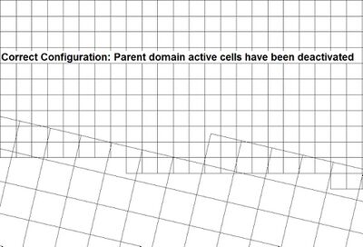
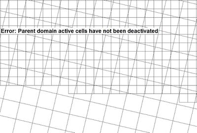
Correct Configuration Incorrect Configuration
- Multiple 2D domain models use a 2d_bc line to define the location of 2D/2D boundary cells. The type attribute associated with the line must be set to "2D" to transfer flow between the neighbouring domains.
- The file containing the GIS layer must be read into the TBC files of both 2D domains. For example, the command below would be read into both TBC files listed in the TCF file:
Read GIS BC == mi\2d_bc_2D_Link_001_L.mif
- The 2d_bc “2D” link line should be snapped to the polygon defining the active/inactive areas.
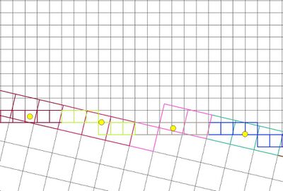
- Flow is transferred between both domains via a series of hidden 1D nodes. The location of the hidden 1D nodes requires consideration. TUFLOW creates these at each vertex along the 2d_bc "2D" link line and also at a regular interval, as defined by the “d” attribute. The hidden 1D nodes act as storage that convey the water from one 2D domain to the other. The water levels along the 2d_bc 2D link line are linearly interpolated using the water levels in the hidden 1D nodes. If in reality the water level profile is not close to linear between vertices, strange flow patterns may occur which can lead to model instability. As such, appropriate resolution of the hidden 1D nodes is an important feature of multiple 2D domain models.
The TCF command Reveal 1D Nodes == ON can be used to view the hidden 1D nodes. The hidden nodes will be written to the nwk_N_check layer. The 2D link can also be reviewed using the 2d_to_2d_check layer; both are shown below.
Some 2d_bc “2D” link line definition advice is provided below:
2D BC "2D" Line Orientation
- The 2d_bc “2D” link line should be orientated perpendicular to the flow direction in areas of moderate to high velocity (>0.5m/s), such as across a river or creek.
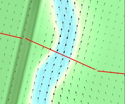
- The 2d_bc “2D” link line can be orientated in any direction within floodplain areas with low velocity (<0.5m/s). The 2d_bc “2D” link line “d” attribute should be used in this situation. This is discussed in the following section.
2D BC "2D" Line Vertex Location and Hidden 1D Node Options
As previously mentioned, flow is transferred between both domains via a series of hidden 1D nodes. TUFLOW creates these at each vertex along the 2d_bc "2D" link line and also at a regular interval, as defined by the “d” attribute.
2d_bc “2D” link line vertices are best located on ridges or embankments, including features that become inundated and drowned out during a simulation.
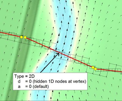
- In regions of moderate to high velocity (>0.5m/s), manual vertex placement on the river banks and natural ridges in addition to a “d” value of 0 is common. Using a “d” value of 0 will create a hidden 1D node at each vertex along the 2d_bc “2D” link line. No intermediate hidden 1D nodes will be created.
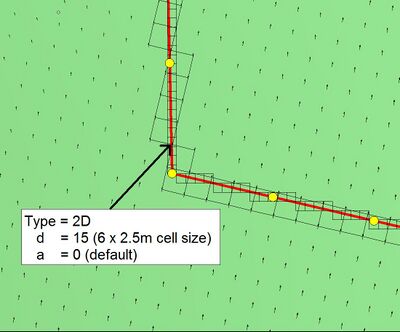
- Model results are less sensitive to the hidden 1D node placement in regions of low velocity (<0.5m/s). Automated placement by using a “d” values greater than 0 is common in this situation. The selected value should be no less than three times the size of the larger cell resolution associated with the 2D/2D boundary. For example, if the model uses a 2.5m and 5m resolution, the “d” attribute should be set no smaller than 15m.
2D BC "2D" Line Storage Multiplier Options
2d_bc “2D” link line “a” attribute defines the storage allocation to each of the hidden 1D nodes. The default value is 2. Increasing the value may improve stability, though but may unacceptably attenuate results. Sensitivity testing has identified the following recommended maximum values:
- Moderate to high velocity area (>0.5m/s): “a” <=6
- Low velocity area (<0.5m/s): “a” <=3
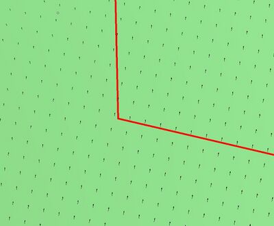
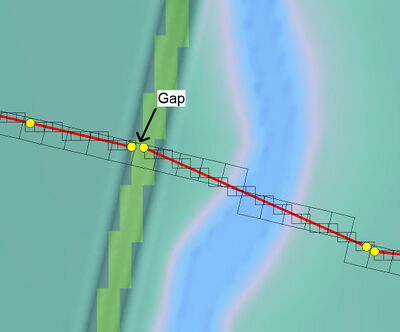
Consider using separate 2d_bc “2D” link lines where there are unique flow paths separated by areas of dry land.
- The 2d_bc “2D” link line should be orientated perpendicular to the flow direction in areas of moderate to high velocity (>0.5m/s), such as across a river or creek.
- The file containing the GIS layer must be read into the TBC files of both 2D domains. For example, the command below would be read into both TBC files listed in the TCF file:
- Example 2D/2D models are available for download from the Example Models page of the Wiki.


