FM Tute M02 MI Define Elevations: Difference between revisions
Jump to navigation
Jump to search
Content deleted Content added
Tuflowduncan (talk | contribs) |
No edit summary |
||
| (6 intermediate revisions by one other user not shown) | |||
| Line 1: | Line 1: | ||
<ol> |
<ol> |
||
=Introduction= |
=Introduction= |
||
This page describes the method for using MapInfo to create a 3D TIN, modifying the zpt elevations to represent the proposed development. Refer to |
This page describes the method for using MapInfo to create a 3D TIN, modifying the zpt elevations to represent the proposed development. Refer to the <u>[https://docs.tuflow.com/classic-hpc/manual/latest/ TUFLOW Manual]</u> for more information on this feature.<br> |
||
=Method= |
=Method= |
||
<li>Copy the contents of the '''Module_data\ |
<li>Copy the contents of the '''Module_data\Module_02\2D_Development''' into the '''TUFLOW\model\mi''' folder. This folder contains the following two layers: |
||
*<b> |
*<b>2d_ztin_M02_development_001_R.mid</b>,and |
||
*<b> |
*<b>2d_ztin_M02_development_001_P.mid</b>. |
||
<li>Open the layer ''' |
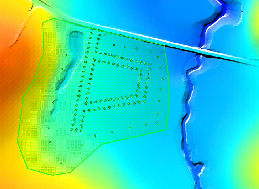
<li>Open the layer '''2d_ztin_M02_development_001_R''' within MapInfo and observe the polygon and its attributes. This polygon defines the area within which we wish to alter the zpt elevations. Any points falling within the polygon are used for creating the TIN surface. The attributes of this polygon have been left blank (are set to 0) as the elevations will be defined in a separate layer. |
||
<li>Open the layer '''' |
<li>Open the layer ''''2d_ztin_M02_development_001_P''' within MapInfo and observe the points and its attributes. These points all have elevations assigned to the ‘Z’ attribute and will be used when generating the TIN. Note that none of the points are snapped to the polygon within the '''2d_ztin_M02_development_001_R''' layer. The elevations of the polygon’s perimeter will therefore be based on the current zpt values (i.e. the zpt values assigned by any prior commands). Later on in this tutorial, we will specify the command used within the tgc to associate the two GIS layers with each other. <br> |
||
[[File:M07 TIN.png|900px]] |
[[File:M07 TIN.png|900px]] |
||
Latest revision as of 09:59, 23 September 2024
- Copy the contents of the Module_data\Module_02\2D_Development into the TUFLOW\model\mi folder. This folder contains the following two layers:
- 2d_ztin_M02_development_001_R.mid,and
- 2d_ztin_M02_development_001_P.mid.
- Open the layer 2d_ztin_M02_development_001_R within MapInfo and observe the polygon and its attributes. This polygon defines the area within which we wish to alter the zpt elevations. Any points falling within the polygon are used for creating the TIN surface. The attributes of this polygon have been left blank (are set to 0) as the elevations will be defined in a separate layer.
- Open the layer '2d_ztin_M02_development_001_P within MapInfo and observe the points and its attributes. These points all have elevations assigned to the ‘Z’ attribute and will be used when generating the TIN. Note that none of the points are snapped to the polygon within the 2d_ztin_M02_development_001_R layer. The elevations of the polygon’s perimeter will therefore be based on the current zpt values (i.e. the zpt values assigned by any prior commands). Later on in this tutorial, we will specify the command used within the tgc to associate the two GIS layers with each other.
- Save and export all layers to MID/MIF format.
Conclusion
The two 2D_tin layers will together modify the zpt elevations in the area of the proposed development. The latter part of this module will demonstrate the command used to write a .tin file to allow for viewing and editing of the TIN directly in SMS. Checks will also be carried out to observe how the TIN has been generated. Please return to the main page of the Flood Modeller Module 2 Tutorial.
Introduction
This page describes the method for using MapInfo to create a 3D TIN, modifying the zpt elevations to represent the proposed development. Refer to the TUFLOW Manual for more information on this feature.
