Arc Extract Breakline from DEM: Difference between revisions
Chris Huxley (talk | contribs) |
|||
| (9 intermediate revisions by 3 users not shown) | |||
| Line 2: | Line 2: | ||
This page outlines the method used to take a line feature class, and extract elevations from DEM for input to TUFLOW breaklines. This is useful if you have a hydraulic control, for example a road embankment that you want to ensure is represented in the model. In this method the elevations will be extracted from the DEM. If detailed survey exists this should be used. This can also be used to process a thalweg / creek centre line. |
This page outlines the method used to take a line feature class, and extract elevations from DEM for input to TUFLOW breaklines. This is useful if you have a hydraulic control, for example a road embankment that you want to ensure is represented in the model. In this method the elevations will be extracted from the DEM. If detailed survey exists this should be used. This can also be used to process a thalweg / creek centre line. |
||
<br> |
<br> |
||
TUFLOW breaklines (2d Z Shape), are a mixture of line and point feature classes. This allows points to be deleted, without deleting the vertices along the line. |
TUFLOW breaklines (2d Z Shape), are a mixture of line and point feature classes. This allows points to be deleted, without deleting the vertices along the line. There are a number of ways of doing this:<br> |
||
'''Method 1''' |
'''Method 1''' |
||
Using the TUFLOW utilities. |
|||
The next two methods are processed within Arc and the general process is to convert a line feature class, to a point feature class and extracting the elevation. Is a multiple step process and we are looking to implement a python script to automate this. |
|||
'''Method 2''' |
|||
# Convert line vertices to points |
# Convert line vertices to points |
||
# Extract elevations directly from DEM |
# Extract elevations directly from DEM |
||
<br> |
<br> |
||
This method requires that the line has been digitised at the high or low point that you are trying to represent. If the vertex on the line, is not at the crest of the ridge, the elevation may be slightly out.<br> |
This method requires that the line has been digitised at the high or low point that you are trying to represent. If the vertex on the line, is not at the crest of the ridge, the elevation may be slightly out.<br> |
||
'''Method |
'''Method 3'''<br> |
||
Method |
Method 3 creates a buffer around each points and can be used to extract the maximum, minimum or average elevation from the DEM within this buffer. This ensures that the control is represented, even if the line does not follow the levee crest or centreline perfectly. The steps involved are: |
||
# Convert line vertices to points |
# Convert line vertices to points |
||
# Create a buffer around each point (specified buffer distance) |
# Create a buffer around each point (specified buffer distance) |
||
| Line 16: | Line 19: | ||
The steps involved in each method are detailed below. |
The steps involved in each method are detailed below. |
||
=Method 1 ( |
=Method 1 (TUFLOW Utilities)= |
||
The asc_to_asc.exe can be used to extract elevations using the method outlined in the following page [[ASC_to_ASC#Extract_Breaklines_from_DEM | asc_to_asc.exe]]. DEM will need to be exported in either the .asc or .flt format. This gives user control over the method for inspection and can insert additional vertice along the line. |
|||
| ⚫ | |||
<ol> |
<ol> |
||
<li>The first step is to create a point feature class from the line, to do this follow the method outlined in the <u>[[Arc_Lines_to_Points | convert lines to points tip.]]</u></li> |
<li>The first step is to create a point feature class from the line, to do this follow the method outlined in the <u>[[Arc_Lines_to_Points | convert lines to points tip.]]</u></li> |
||
<li>To |
<li>To inspect the elevations at each of the points, follow the method outlined in the <u>[[Arc_Assign_DEM_Value_to_Points | this Arc GIS Tip]].</u> This will create a new point feature class which contains all of the original attributes, as well as the raster value. |
||
<li>TUFLOW uses the elevation in the '''Z''' attribute, to update this, open the attribute table, right click on the Z attribute and select ''Field Calculator''.</li> |
|||
</li>Make the layer |
|||
<li>In the dialogue, simply double click on the raster value attribute.</li> |
|||
[[File:Arc Breaklines from DEM 02.jpg|400px]] |
|||
</ol> |
</ol> |
||
| ⚫ | |||
=Method 3 (Region Inspection)= |
|||
<ol> |
<ol> |
||
<li>As with the method above, the first step is to create a point feature class from the line, to do this follow the method outlined in the <u>[[Arc_Lines_to_Points | convert lines to points tip.]]</u></li> |
|||
<li>The next step is to create a buffer around each of the points. To do this, from the toolboxes select ''Analysis >> Proximity >> Buffer''.</li> |
|||
[[File:Arc Buffer Point 01.jpg]] |
|||
<br><br> |
|||
<li>In the buffer dialogue, set the input layer as the newly created points (step 1). Set the output file (this is a temporary table and will not be used as an input to TUFLOW). Set the distance type to linear and set the required distance. This distance will depend on the width of the feature you are trying to represent and the TUFLOW cell size.</li> |
|||
</ol> |
</ol> |
||
<br> |
|||
{{Tips Navigation |
|||
|uplink=[[ArcGis_Tips | Back to ArcGIS]]}} |
|||
Latest revision as of 04:54, 3 February 2015
Introduction
This page outlines the method used to take a line feature class, and extract elevations from DEM for input to TUFLOW breaklines. This is useful if you have a hydraulic control, for example a road embankment that you want to ensure is represented in the model. In this method the elevations will be extracted from the DEM. If detailed survey exists this should be used. This can also be used to process a thalweg / creek centre line.
TUFLOW breaklines (2d Z Shape), are a mixture of line and point feature classes. This allows points to be deleted, without deleting the vertices along the line. There are a number of ways of doing this:
Method 1
Using the TUFLOW utilities.
The next two methods are processed within Arc and the general process is to convert a line feature class, to a point feature class and extracting the elevation. Is a multiple step process and we are looking to implement a python script to automate this.
Method 2
- Convert line vertices to points
- Extract elevations directly from DEM
This method requires that the line has been digitised at the high or low point that you are trying to represent. If the vertex on the line, is not at the crest of the ridge, the elevation may be slightly out.
Method 3
Method 3 creates a buffer around each points and can be used to extract the maximum, minimum or average elevation from the DEM within this buffer. This ensures that the control is represented, even if the line does not follow the levee crest or centreline perfectly. The steps involved are:
- Convert line vertices to points
- Create a buffer around each point (specified buffer distance)
- Extract desired elevation statistic (max, min, mean) for each region
- Assign elevation from buffer to point
The steps involved in each method are detailed below.
Method 1 (TUFLOW Utilities)
The asc_to_asc.exe can be used to extract elevations using the method outlined in the following page asc_to_asc.exe. DEM will need to be exported in either the .asc or .flt format. This gives user control over the method for inspection and can insert additional vertice along the line.
Method 2 (Point Inspection)
- The first step is to create a point feature class from the line, to do this follow the method outlined in the convert lines to points tip.
- To inspect the elevations at each of the points, follow the method outlined in the this Arc GIS Tip. This will create a new point feature class which contains all of the original attributes, as well as the raster value.
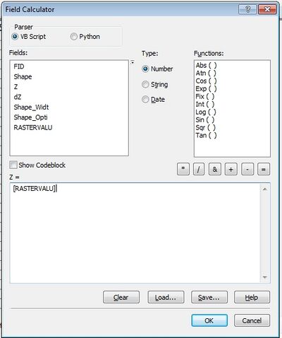
- TUFLOW uses the elevation in the Z attribute, to update this, open the attribute table, right click on the Z attribute and select Field Calculator.
- In the dialogue, simply double click on the raster value attribute.

Method 3 (Region Inspection)
- As with the method above, the first step is to create a point feature class from the line, to do this follow the method outlined in the convert lines to points tip.
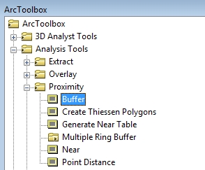
- The next step is to create a buffer around each of the points. To do this, from the toolboxes select Analysis >> Proximity >> Buffer.
- In the buffer dialogue, set the input layer as the newly created points (step 1). Set the output file (this is a temporary table and will not be used as an input to TUFLOW). Set the distance type to linear and set the required distance. This distance will depend on the width of the feature you are trying to represent and the TUFLOW cell size.

| Up |
|---|