Using ReFH2 to Generate TUFLOW Boundary Inputs: Difference between revisions
Tuflowduncan (talk | contribs) |
Tuflowduncan (talk | contribs) |
||
| Line 18: | Line 18: | ||
=Creating Design Rainfall and Runoff within ReFH2 for use with TUFLOW= |
=Creating Design Rainfall and Runoff within ReFH2 for use with TUFLOW= |
||
To generate rainfall or runoff using ReFH2, firstly open the ReFH2 software and create a new ReFH project.<br> |
Both rainfall and runoff can be generated within ReFH2 and used within TUFLOW either as a direct rainfall boundary or a flow boundary. To generate rainfall or runoff using ReFH2, firstly open the ReFH2 software and create a new ReFH project.<br> |
||
<br> |
<br> |
||
[[File:New Project.png|800px]]<br> |
[[File:New Project.png|800px]]<br> |
||
<br> |
<br> |
||
Use the ‘Import from file’ option to import the XML files. Importing the xml file will populate the parameters. The XML data |
Use the '''‘Import from file’''' option to import the XML files. Importing the xml file will populate the parameters. The XML data is available is available in catchment data or point data format. When using the point data format, these do not have an area associated with them. Therefore, the user will need to specify the area of the plot that you are interested in (if required this can also be edited later). <br> |
||
<br> |
<br> |
||
[[File:Point_Descriptors.png|400px]]<br> |
[[File:Point_Descriptors.png|400px]]<br> |
||
| Line 31: | Line 31: | ||
[[File:Catchment_Descriptors.png|400px]]<br> |
[[File:Catchment_Descriptors.png|400px]]<br> |
||
<br> |
<br> |
||
Once the parameters have been imported, and the country specified, apply the parameters and choose to move to the next page. On the next page |
Once the parameters have been imported, and the country specified, apply the parameters and choose to move to the next page. On the next page the user can choose which rainfall model to use, FEH1999 or FEH2013. It’s possible to specify the design rainfall return periods of interest and ReFH2 will automatically calculate the recommended duration and suggest an appropriate timestep that meets the requirement that the duration must be an odd multiple of the time step. The recommended duration should normally be used, although both values can be edited directly to provide the duration that is required. The XML file from the FEH2013 website contains the rainfall depths for a number of pre-defined return period/duration combinations. For those return period/duration combinations that are not pre-defined, ReFH2 undertakes a two-way interpolation process. ReFH2 will then generate the design rainfall hyetograph based on the rainfall depth and the FSR approach.<br> |
||
<br> |
<br> |
||
[[File:FEH_2013_Design_Rainfall.png|400px]]<br> |
[[File:FEH_2013_Design_Rainfall.png|400px]]<br> |
||
<br> |
<br> |
||
On the right hand side you can see the calculated Areal Reduction Factor and Seasonal Correction Factors which will be applied. The rainfall profile can vary depending on the season selected (summer or winter) and the seasonal correction factor and areal reduction factor are both applied to the rainfall hyetograph to obtain the correct design rainfall hyetograph. |
On the right hand side you can see the calculated Areal Reduction Factor and Seasonal Correction Factors which will be applied to the rainfall depth. The rainfall profile can vary depending on the season selected (summer or winter) and the seasonal correction factor and areal reduction factor are both applied to the rainfall hyetograph to obtain the correct design rainfall hyetograph. |
||
Once the Return periods and durations have been defined then click next. This brings up the various parameters together with the rainfall hyetographs and runoff hydrographs for the various return periods. The rainfall hyetographs and runoff are available as rural and urbanised scenarios.<br> |
Once the Return periods and durations have been defined then click next. This brings up the various parameters together with the rainfall hyetographs and runoff hydrographs for the various return periods. The rainfall hyetographs and runoff are available as rural and urbanised scenarios.<br> |
||
<br> |
<br> |
||
| Line 43: | Line 43: | ||
<ol> |
<ol> |
||
<li> Design Rainfall |
<li> Design Rainfall |
||
<li> Urban |
<li> Urban Net Rainfall |
||
<li> Rural |
<li> Rural Net Rainfall |
||
<li> Sewer Loss |
<li> Sewer Loss |
||
<li> Total |
<li> Total Net Rain |
||
<li> Direct Runoff |
<li> Direct Runoff |
||
<li> Baseflow |
<li> Baseflow |
||
| Line 65: | Line 65: | ||
[[File:Urbanisation.png]]<br> |
[[File:Urbanisation.png]]<br> |
||
<br> |
<br> |
||
The grids can then be exported to csv using the ‘Export Grid’ option. This exports the time-varying grids for all return periods and all design outputs.<br> |
The grids can then be exported to csv using the '''‘Export Grid’''' option. This exports the time-varying grids for all return periods and all design outputs.<br> |
||
<br> |
<br> |
||
[[File:ReFH2 Outputs.png]]<br> |
[[File:ReFH2 Outputs.png]]<br> |
||
<br> |
<br> |
||
The relevant data can then be copied into the TUFLOW bc_dbase folder and referenced by the |
The relevant data can then be copied into the TUFLOW bc_dbase folder and referenced by the '''bc_dbase.csv''' file as appropriate (see Module 08 for an example of applying direct rainfall boundary conditions for example). |
||
The gross design rainfall or total net rainfall can be applied to directly to the 2D domain using a 2D_RF polygon to distribute the rainfall. Multiple RF polygons can be used to spatially distribute the rainfall if required. |
The gross design rainfall or total net rainfall can be applied to directly to the 2D domain using a 2D_RF polygon to distribute the rainfall. Multiple RF polygons can be used to spatially distribute the rainfall if required. |
||
The total runoff (or rainfall) can be applied directly to a 2D_SA polygon, to apply the inflow to an area of the 2D mesh. There are a number of options for distributing flows in this instance, these are:- |
The total runoff (or rainfall) can be applied directly to a 2D_SA polygon, to apply the inflow to an area of the 2D mesh. There are a number of options for distributing flows in this instance, these are:- |
||
| Line 79: | Line 79: | ||
</ol> |
</ol> |
||
<br> |
<br> |
||
Only distributing to all cells equally represents the surface water mechanism which routes flow from the point it falls, the other approaches work on the assumption that the flow ends up either at the lowest cells, at 1D pits or within channels within the model domain. |
Only distributing to all cells equally represents the surface water mechanism which routes flow from the point it falls, the other approaches work on the assumption that the flow ends up either at the lowest cells, at 1D pits or within channels within the model domain.<br> |
||
It is also possible to apply the total runoff to a 1D or 2D point or line using the 1D_BC or 2D_BC layers. The user can, if desired, split the total runoff by applying the direct runoff component to one model location and the baseflow component to another location. |
It is also possible to apply the total runoff to a 1D or 2D point or line using the 1D_BC or 2D_BC layers. The user can, if desired, split the total runoff by applying the direct runoff component to one model location and the baseflow component to another location. |
||
<br> |
<br> |
||
Revision as of 00:43, 5 March 2019
THIS PAGE IS CURRENTLY UNDER CONSTRUCTION
Introduction
In 2016, the Centre of Ecology and Hydrology (CEH) and Wallingford Hydro Solutions (http://www.hydrosolutions.co.uk) released another version of the revitalised rainfall-runoff model (ReFH2) which allows users to generate design flows and hydrographs from given rainfall events for both catchment and development sites. ReFH2 is a rainfall-runoff model specifically applicable to England, Wales and parts of Scotland. It takes inputs from the Flood Estimation Handbook 2013 (FEH2013) website and generates design rainfall events and provides a method for calculating design runoff from subcatchments.
For a full description of the approaches, the reader is referred to their document which can be freely accessed at:-
http://files.hydrosolutions.co.uk/refh2/ReFH2_Technical_Report.pdf. The ReFH2 method is available within the ReFH2 software
To use the ReFH2, the software must be installed locally and a licence must be obtained from Wallingford HydroSolutions. The ReFH2 software can be installed from http://files.hydrosolutions.co.uk/refh2/latest.
FEH 2013 Rainfall
FEH2013 is a new method for generating design rainfall hyetographs, superseding the FEH1999 method. In order to generate the design rainfall, the user obtains design rainfall depths from the FEH2013 web service at https://fehweb.ceh.ac.uk for pre-defined return period/duration combinations. This requires a log on and user credits to purchase the data for the desired location. Data is available at a river catchment scale and as a point value. Both of these provide XML containing the rainfall depths. This is then imported into the ReFH2 software to generate hyetographs based on Flood Studies Reports (FSR) approaches.
ReFH2 Runoff
ReFH2 is the new method for the calculation of runoff. It hasn’t changed significantly from the original ReFH approach for which equations are publicly available, although there has been a mass balance closure improvement to the runoff model. There has however, been a change to the initial conditions, BF0 and Cini (initial baseflow and initial soil moisture, C, respectively) and there is an additional parameter, alpha. The data contained in the XML from the FEH2013 website also provides the catchment descriptors to calculate the necessary model parameters within ReFH 2 from which the runoff hydrograph is developed.
Creating Design Rainfall and Runoff within ReFH2 for use with TUFLOW
Both rainfall and runoff can be generated within ReFH2 and used within TUFLOW either as a direct rainfall boundary or a flow boundary. To generate rainfall or runoff using ReFH2, firstly open the ReFH2 software and create a new ReFH project.
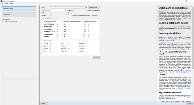
Use the ‘Import from file’ option to import the XML files. Importing the xml file will populate the parameters. The XML data is available is available in catchment data or point data format. When using the point data format, these do not have an area associated with them. Therefore, the user will need to specify the area of the plot that you are interested in (if required this can also be edited later).
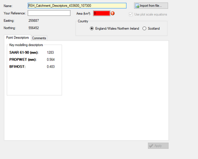
Once an area value has been provided then it is possible to generate the rainfall hyetographs and runoff hydrographs and apply to TUFLOW in the same manner as for catchment descriptors.
The user will then choose which country the data corresponds to. The ReFH2 programme included the development of Scotland specific algorithms to estimate the model parameters from the catchment descriptors. The choice of Scotland will mean that the alpha correction factor is not applied.
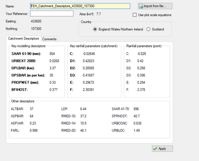
Once the parameters have been imported, and the country specified, apply the parameters and choose to move to the next page. On the next page the user can choose which rainfall model to use, FEH1999 or FEH2013. It’s possible to specify the design rainfall return periods of interest and ReFH2 will automatically calculate the recommended duration and suggest an appropriate timestep that meets the requirement that the duration must be an odd multiple of the time step. The recommended duration should normally be used, although both values can be edited directly to provide the duration that is required. The XML file from the FEH2013 website contains the rainfall depths for a number of pre-defined return period/duration combinations. For those return period/duration combinations that are not pre-defined, ReFH2 undertakes a two-way interpolation process. ReFH2 will then generate the design rainfall hyetograph based on the rainfall depth and the FSR approach.
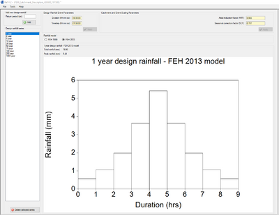
On the right hand side you can see the calculated Areal Reduction Factor and Seasonal Correction Factors which will be applied to the rainfall depth. The rainfall profile can vary depending on the season selected (summer or winter) and the seasonal correction factor and areal reduction factor are both applied to the rainfall hyetograph to obtain the correct design rainfall hyetograph.
Once the Return periods and durations have been defined then click next. This brings up the various parameters together with the rainfall hyetographs and runoff hydrographs for the various return periods. The rainfall hyetographs and runoff are available as rural and urbanised scenarios.
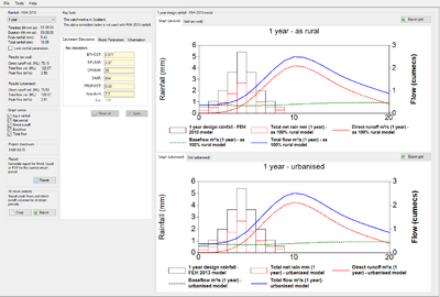
Data can be viewed either as graphs or as grids. The available data includes the following for the selected return period and duration:-
- Design Rainfall
- Urban Net Rainfall
- Rural Net Rainfall
- Sewer Loss
- Total Net Rain
- Direct Runoff
- Baseflow
- Total Flow
The return period can be varied using the dropdown menu in the Rainfall section.
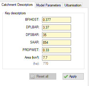
The catchment descriptors (BFIHOST, DPLBAR, DPSBAR, SAAR, PROPWET and Area) can all be edited should a sensitivity analysis be required.
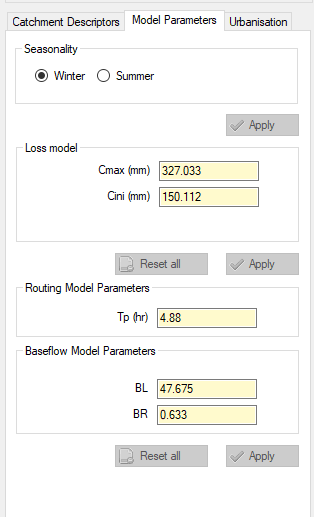
The model parameters section allows the user to specify the seasonality and other parameters, again for sensitivity analysis. Changing the seasonality will change the seasonal correction factor for the rainfall.
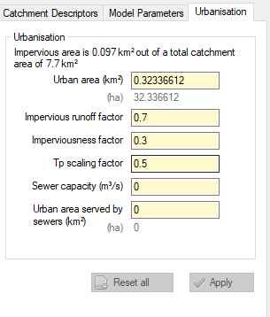
The urbanisation tab allows the user to estimate the impact of urbanisation for catchments as well as greenfield and post development peak runoff rates for development sites.
The grids can then be exported to csv using the ‘Export Grid’ option. This exports the time-varying grids for all return periods and all design outputs.

The relevant data can then be copied into the TUFLOW bc_dbase folder and referenced by the bc_dbase.csv file as appropriate (see Module 08 for an example of applying direct rainfall boundary conditions for example).
The gross design rainfall or total net rainfall can be applied to directly to the 2D domain using a 2D_RF polygon to distribute the rainfall. Multiple RF polygons can be used to spatially distribute the rainfall if required.
The total runoff (or rainfall) can be applied directly to a 2D_SA polygon, to apply the inflow to an area of the 2D mesh. There are a number of options for distributing flows in this instance, these are:-
- Flow is distributed firstly to the lowest cell and then to the wet cells,
- Distributed to all 2D cells connecting to 1D pits,
- Distributed to all cells equally,
- Distributed using streamlines to define watercourses.
Only distributing to all cells equally represents the surface water mechanism which routes flow from the point it falls, the other approaches work on the assumption that the flow ends up either at the lowest cells, at 1D pits or within channels within the model domain.
It is also possible to apply the total runoff to a 1D or 2D point or line using the 1D_BC or 2D_BC layers. The user can, if desired, split the total runoff by applying the direct runoff component to one model location and the baseflow component to another location.
Using TUFLOW Events
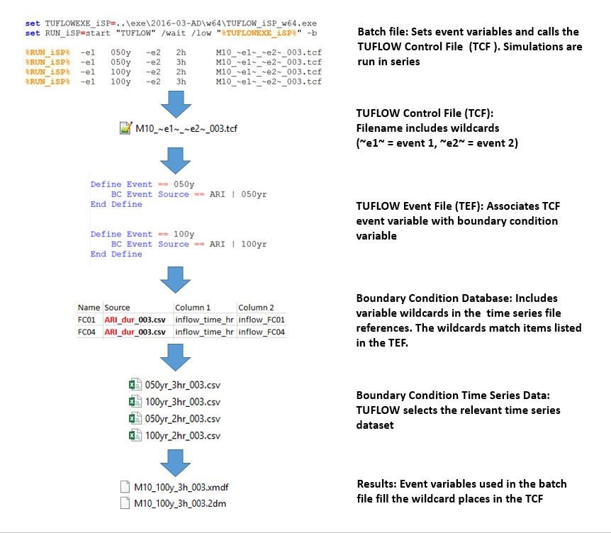
In most applications there will be a requirement to run a number of return period design events, potentially with a number of different durations. TUFLOW’s event options makes the management of these simulations a simpler process. TUFLOW’s event management structure uses a variety of wildcard characters in the TCF file and the boundary condition database for event inputs. The wildcards are replaced with user defined event specific acronyms when a simulation is run from a batch file. This will significantly reduce the number of repetitive files required to execute a project. TUFLOW event management is shown in the following image.
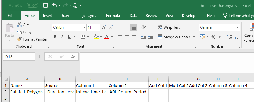
TUFLOW’s event management will be of use when running multiple return periods and durations events from ReFH2. Currently a single CSV file will be generated for a number of return periods from the ReFH2 software. Where multiple durations are used, this will generate multiple csv files. Each of these can be defined as a separate source csv file. For instance, in the bc_dbase file we can have the following where _Duration_ is the wildcard to specify the individual csv files references the different return period hyetographs for each duration.
The wildcard also works on column 2 as well. So we can use this to use the return period as specified in the batch file to read the relevant column from a csv file exported directly from ReFH2. For example, in the file directly exported from ReFH2, the 1 year net rainfall column is called “Total net rain mm (1 year) - as 100% rural model”. We can set column 2 to look for the ‘Total net rain mm (ARI) – as 100% rural model’ bc_dbase setup to read the relevant net rainfall column for the return period of interest based on the ARI wildcard.
Note: The exported csv file has time in HH:MM:SS. This would need to converting into hours. Also the exported rainfall profiles do not have the first value set to 0mm. TUFLOW requires that the first value in the rainfall hyetograph is set to 0mm. This is not neccesary for flow data
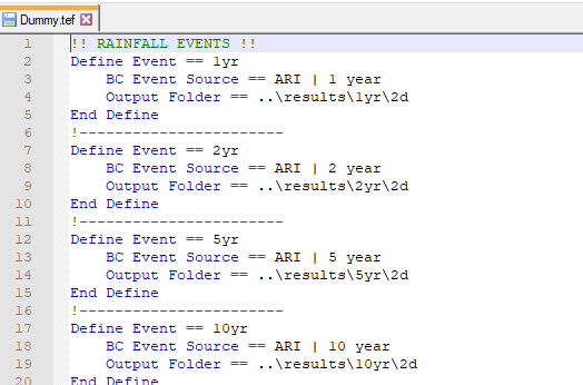
Once the bc_base has been set up then a .tef file can be generated which populates the ARI variable above with the relevant ARI for the specific question. The tef file also creates anew new output folder for each return period.
The .tcf file can be named accordingly for example, Dummy_M01_~e1~_001.tcf, and the batch file commands used to set the ~e1~ value.
Start "Tuflow" /wait ".. \2018-03\TUFLOW_iSP_w64.exe" -e1 1yr "Dummy_m01_~e1~_001.tcf"
Start "Tuflow" /wait "..\2018-03\TUFLOW_iSP_w64.exe" -e1 2yr "Dummy_m01_~e1~_001.tcf"
Start "Tuflow" /wait "..s\2018-03\TUFLOW_iSP_w64.exe" -e1 5yr "Dummy_m01_~e1~_001.tcf"
This will then run the 3 return periods (1yr, 2yr and 5 year).
Summary
This post provides instructions of how to obtain direct rainfall and inflow inputs from the ReFH2 software for use within a TUFLOW model. This requires the input of data from the FEH2013 website and the selection of the appropriate return period, duration combinations of which the user is interested. This outputs the time-varying rainfall and total runoff (as well as runoff contributions) which can be exported for use within TUFLOW. Future development in this area will look to automate some of this process with a plugin.
