MI Display Vertices on Objects: Difference between revisions
Created page with 'There are a number of TUFLOW layers which must be snapped together to ensure connectivity. For example in the 2d_bc the connection "CN" type lines must be snapped to vertices on ...' |
No edit summary |
||
| Line 8: | Line 8: | ||
[[File:Tute M01 MI status bar.png|none|500px|Status bar with snap enabled|frame]] |
[[File:Tute M01 MI status bar.png|none|500px|Status bar with snap enabled|frame]] |
||
<br> |
|||
{{Tips Navigation |
|||
|uplink=[[MapInfo_Tips | Back to MapInfo Tips And Tricks]] |
|||
}} |
|||
Latest revision as of 16:50, 9 September 2011
There are a number of TUFLOW layers which must be snapped together to ensure connectivity. For example in the 2d_bc the connection "CN" type lines must be snapped to vertices on the "HX" type boundary line. It is often convenient to display the location of the vertices to make this easier.
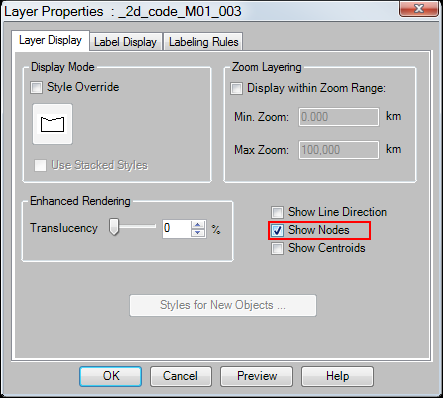
To make the vertices visible, in the Layer Control right click on the layer you want the vertices visible and select Layer Properties to bring up the dialogue below. Tick Show Nodes (highlighted in red below). the vertices should now be visible, these will display as small dark blue squares.
If snapping to these vertices ensure that the "Snap" tool is enabled: this can be toggled on / off by pressing the “S” key, when enable the word SNAP is displayed in status bar along the bottom of the screen. If the Status bar is not visible at the bottom of your MapInfo window this can be turned on by navigating to the Options menu and selecting "Show Status Bar".


| Up |
|---|