Tute M02 SMS 1d2d Link Archive: Difference between revisions
Created page with "=Introduction= This page describes the process of using SMS to create links between the 1D culverts and the 2D model. Three methods are described, this is done to demonstrate..." |
|||
| Line 66: | Line 66: | ||
</ol> |
</ol> |
||
We have defined three different methods of linking 1D with 2D domain. As already mentioned, any one of these three methods can be used to defined the connection. |
We have defined three different methods of linking 1D with 2D domain. As already mentioned, any one of these three methods can be used to defined the connection. |
||
Save the SMS project and move on to the section "[[Tutorial_Module02_Archive# |
Save the SMS project and move on to the section "[[Tutorial_Module02_Archive#Simulation_Control_Files_Updates | Simulation Control Files Updates]]." |
||
Latest revision as of 13:29, 5 April 2024
Introduction
This page describes the process of using SMS to create links between the 1D culverts and the 2D model. Three methods are described, this is done to demonstrate the available methods. Generally one of the described methods would be used.
The methods described are:
- Using a point object in the 2d_bc type layer;
- Using a line object in the 2d_bc type layer; and
- Using a point object in a 1d_nwk layer.
Methods
The culverts have now been defined but we have to specify how the culvert will be linked to the 2D domain. We will do this by using a combination of two new coverages.
We will use a different alternate method in each culvert:
- Alternate 1: Culvert FC04.1_C
- Alternate 2: Culvert FC01.2_R
- Alternate 3: Culvert FC01.1_R
Alternate 1: Point object in 2d_bc type layer
In this method, a point is created in 1D/2D BCs and Links coverage and that point will be used to establish a connection between 1D and 2D domains. Follow the following steps:
- Create a new TUFLOW 1D/2D BCs and Links coverage named “Culvert_BC” (right click on Map Data – New Coverage).
- Zoom in around the culvert FC04.1_C (right side of the domain).
- Click on "Culvert_BC" coverage to make it active. On activating this coverage, if the culvert arc disappears from the display then select Display | Display Options. Under Map category, toggle on Inactive Coverage option to make inactive coverage visible. This option is on the lower right side of the display options dialog.
- Select Create Feature Point tool and click at the upstream and downstream ends of the culvert. While creating these new nodes you need to make sure that they snap to the ends of the culvert arc.
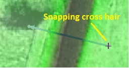
- Note: In this process, two different coverages are involved (Culverts and Culvert_BC). We are creating a node on Culvert_BC coverage and snapping this node to the edge of culvert arc in Culverts coverage. SMS has a built in function to turn snapping on which enables snapping the feature point to nearest node in active as well as inactive coverages. The snapping is On by default, if it is turned off, press S key on the keyboard to turn it on or off. If the snapping is on, you can see a little cross hair appear as you approach closer to a node.
- Click on Select Feature Point tool and double click on this newly created node to bring up Boundary Conditions dialog.
- Change Node type to "2D" and Type to "Flow Source from 1D Model (SX)"
- Make sure that Adjust z elevation in each cell center is toggled off.
- Make sure that Do not set 1D Water Level is toggled off.
- Click Ok.

Alternate 2: Line object in 2d_bc type layer

In this method, the connection between 1D and 2D domains is established using an arc. The reason for using a line object rather than a point object is to allow the culvert to connect to more than one 2D cell. This is important where the dimensions of the 1D channel or culvert are greater than the 2D cell size. For this box culvert there are 5 barrels each with a width of 2.4 metres. This could cause unstability when connected to a single 2D cell.
We will be using two different coverages to define this linkage. A bc coverage will contain arcs that specify where water goes from the 2D domain to the 1D domain and from the 1D domain back into the 2D domain. Similarly a 1D/2D connections coverage will link the boundary condition arcs to the appropriate ends of the 1D network.
We will use this linkage on FC01.2_R. To setup the “Flow Source from 1D” boundary condition follow these steps:
- Click on Culvert_BC coverage to make it active.
- Zoom in around the culvert FC01.2_R.
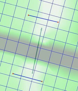
- Create two arcs near each end of the culvert covering about three grid cells as shown in the figure to the right. Water from each 2D cell that the arc selects will be conveyed in/out of the 1D domain. The arcs do not need to overlap with the culvert arc.
- Using the Select Arc Tool, select both arcs, right click and select "Attributes".
- Change the type to Flow Source from 1D Model (SX).
- Make sure that Do not set 1D Water Level is toggled off.
- Click OK.

Next we need to specify which culvert points are connected to the Flow Source arcs. This is done using a 1D/2D Linkage coverage. The linkage arcs must be snapped to the endpoints of the network arc and the flow source arcs. Make sure snapping is turned on in SMS. (Note: See Alternate 1, step 4 to see how snapping is turned on/off)
- Create a new coverage of type TUFLOW 1D/2D Connections and rename it to “Culvert_Connections.”
- As soon as this coverage is created SMS will prompt you to select a BC coverage which will be associated with this connections coverage. Click on Culvert_BC coverage and click OK.
- Click on Culvert_Connections coverage to make it active. On activating this coverage, if the Flow source arcs disappear, then you will need to turn on the display of inactive coverage.
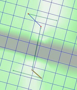
- On "Culvert_Connections" coverage, create arcs from the endpoints of each Flow Arc to the appropriate endpoint of the culvert arc as shown in the figure. Make sure the ends of these lines snap to the flow source arcs on the underlying coverage which will happen automatically as long as the coverages are turned on.
- Note: Three different coverages are involved in this step Culverts, Culvert_BC and Culvert_Connections. The new arc you just created is on Culvert_Connection coverage, one end of which is snapped to the arc in Culverts coverage and the other end to the arc in Culvert_Connections coverage.
- Save your SMS Project
Alternate 3: Point object in 1d_nwk type layer

In this method, the link between 1D and 2D domains are defined using node(s) in the 1D Network. We will use this linkage on FC01.1_C. To setup the “Flow Source from 1D” boundary condition follow these steps:
- Click on Culverts coverage to make it active
- Zoom in around the culvert FC01.1_C.
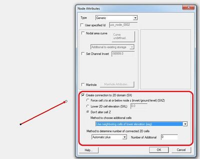
- Click on Select Feature Point tool and double click at one of the end nodes in the culvert arc to open "Node Attributes" dialog
- In this dialog, toggle on Create connection to 2D domain (SX), make sure Don't alter cell Z is toggled on. Click Ok. (See figure on the right)
- Repeat the same for other node of the same culvert.
We have defined three different methods of linking 1D with 2D domain. As already mentioned, any one of these three methods can be used to defined the connection. Save the SMS project and move on to the section " Simulation Control Files Updates."