FM Tutorial M02 QGIS SHP Pipe Network: Difference between revisions
Created page with "<ol> =Introduction= This page describes the method for using QGIS to create the GIS based layers representing the pipe network. Two layers will be created each representing t..." |
No edit summary |
||
| Line 24: | Line 24: | ||
|} |
|} |
||
<br> |
<br> |
||
The attributes are described completely in |
The attributes are described completely in <u>[https://docs.tuflow.com/classic-hpc/manual/2025.1/OneD-Domains-1.html#tab:tab-CulvertsAttributeDescriptions Table 5.5]</u> of the TUFLOW Manual. The attributes that we have populated, define:<br> |
||
*The 1d_nwk type. In this case, we have specified culverts with a circular shape. |
*The 1d_nwk type. In this case, we have specified culverts with a circular shape. |
||
*The Manning’s n value of the culvert. |
*The Manning’s n value of the culvert. |
||
| Line 46: | Line 46: | ||
|} |
|} |
||
<br> |
<br> |
||
Note that although the same layer (1d_nwk) has been used to define the pits of the pipe network as for the culverts, different attributes have been populated. Refer to |
Note that although the same layer (1d_nwk) has been used to define the pits of the pipe network as for the culverts, different attributes have been populated. Refer to |
||
<u>[https://docs.tuflow.com/classic-hpc/manual/2025.1/OneD-Domains-1.html#tab:tab-CulvertsAttributeDescriptions Table 5.5]</u> and <u>[https://docs.tuflow.com/classic-hpc/manual/2025.1/OneD-Domains-1.html#tab:tab-PitsModelNetwork Table 5.24]</u> of the TUFLOW Manual for further information on how the attributes of the 1d_nwk layer differ between nodes and channels. The attributes that we have populated for the pits, define:<br> |
|||
*The type of pit channel. In this case, a type ‘Q’ specifies the flow is to be defined by a depth-discharge curve from a user defined database. This database will be created in the next steps of this module. |
*The type of pit channel. In this case, a type ‘Q’ specifies the flow is to be defined by a depth-discharge curve from a user defined database. This database will be created in the next steps of this module. |
||
*AB is the name of the pit inlet type referenced within the pit database. |
*AB is the name of the pit inlet type referenced within the pit database. |
||
Revision as of 01:29, 3 July 2025
- Copy the GIS layers 1d_nwk_FMT_M02_Pipes_001_L.shp and 1d_nwk_FMT_M02_Pits_001_P.shp within Module_data\Module_02\Pipe_Network into the TUFLOW\model\gis folder.
- Open the layer 1d_nwk_FMT_M02_Pipes_001_L.shp in QGIS. This contains polylines representing the culverts that make up the pipe network.
- A number of the attributes within the 1d_nwk_FMT_M02_Pipes_001_L.shp layer have not been populated. Turn on Toggle Editing for the layer and add the following attributes to all objects leaving all other attributes unchanged. Make use of the ‘'Update All'’ function as previously explained to update all objects at the same time.
Attribute Value Type C n_or_n_F 0.015 US_Invert -99999 DS_Invert -99999 Number_of 1
The attributes are described completely in Table 5.5 of the TUFLOW Manual. The attributes that we have populated, define:
- The 1d_nwk type. In this case, we have specified culverts with a circular shape.
- The Manning’s n value of the culvert.
- The upstream invert level of the pipes. When -99,999 is specified, the invert level will be taken from a manually created node or pit at the upstream end of the culvert. Refer to the next steps in this module where these inverts will be defined by creating pits.
- The downstream invert level of the pipes. The same rules as for the upstream invert applies when specifying -99,999.
- The number of identical pipes in parallel.
- Open the layer 1d_nwk_FMT_M02_Pits_001_P.shp in QGIS. This contains digitised points that represent the pits of the pipe network through which water can transfer to and from the overlying floodplain.
- A number of the attributes within the 1d_nwk_FMT_M02_Pits_001_P.shp layer have not been populated. Toggle Editing for the layer and add the following attributes to all objects leaving all other attributes unchanged. Again, make use of the ‘Update All’ function in QGIS to update all objects at the same time:
Attribute Value Type Q Inlet_Type AB Conn_1D_2D SXL
Note that although the same layer (1d_nwk) has been used to define the pits of the pipe network as for the culverts, different attributes have been populated. Refer to Table 5.5 and Table 5.24 of the TUFLOW Manual for further information on how the attributes of the 1d_nwk layer differ between nodes and channels. The attributes that we have populated for the pits, define:
- The type of pit channel. In this case, a type ‘Q’ specifies the flow is to be defined by a depth-discharge curve from a user defined database. This database will be created in the next steps of this module.
- AB is the name of the pit inlet type referenced within the pit database.
- Specifying SXL for the ‘Conn_2D’ attribute automatically creates a 2D SX connection at the 2D cell within which the 1D pit is located. In addition, the ZC elevation of the cell will be lowered by the amount specified in the ‘US_Invert’ attribute (0.1m), and the upstream invert of the pit channel set to the lowered 2D cell elevation. This is useful to help trap the water into the pit as it flows overland in the 2D domain.
- Open the layer 1d_x1d_FMT_M01_nwk_001_P.shp created in Flood Modeller Tutorial 1. Note that the pipe network has been digitised to outfall to the watercourse represented within the Flood Modeller Network. We will manually specify the downstream invert levels of Pipe16 and Pipe18 as the discharge point of the pipe network is above the bed level of the watercourse. Use the Info tool and click on each pipe in turn and change the ‘DS_Invert’ attribute for both pipes from -99,999 to 38m.
- Save both 1d_nwk_FMT_M02_Pipes_001_L.shp and 1d_nwk_FMT_M02_Pits_001_P.shp.
- The Pit Inlet Database has been created and can be found within Module_data\Module_02\Pipe_Network. Copy the csv files pit_inlet_curves.csv and pit_inlet_dbase.csv into a new folder entitled pit_dbase within the TUFLOW folder.
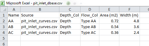
- Open the pit_inlet_dbase.csv file. The Pit Inlet Database is similar to the Boundary Condition Database in that it references an external source file and relates this to corresponding GIS objects within the model.
The first column contains the name of pit inlet type as referenced in the Inlet_Type attribute that was specified within the 1d_nwk_FMT_M02_Pits_001_P.shp layer. The second column contains the name of the source .csv file that contains the depth-discharge curve. The third and fourth columns are the heading labels of the depth and discharge columns respectively in the source .csv file. The fifth and sixth columns are the inlet’s nominated full flow area in m2 and flow width in m. Section 5.11.3 of the TUFLOW Manual provides further information on the Pit Inlet Database.
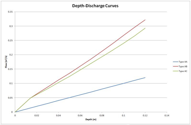
- Open the pit_inlet_curves.csv file. This contains the depth-discharge curves for each pit inlet type which are referenced within the Pit Inlet Database. The curve for pit inlet type AB will be applied to all pits within this tutorial model.
Conclusion
1d_nwk layers have been created representing the culverts and pits that make the pipe network that of the proposed development. The layers have made use of an automated function to link the pits to the 2D domain to allow for the exchange of water between the pipe network and the floodplain. A Pit Inlet Database has been created to define a depth-discharge relationship at each pit. Please return to the main page of the Flood Modeller Tutorial 2.
Introduction
This page describes the method for using QGIS to create the GIS based layers representing the pipe network. Two layers will be created each representing the culverts and pits. The pipe network will be connected to the 2D model domain and and a depth-discharge relationship defined at the pits via the creation of a Pit Inlet Database.
Method
Pit Inlet Database

