MIKE Flood to TUFLOW: Difference between revisions
Ellis Symons (talk | contribs) |
Ellis Symons (talk | contribs) No edit summary |
||
| Line 9: | Line 9: | ||
* xsGenerator.exe (for MIKE11 conversion) |
* xsGenerator.exe (for MIKE11 conversion) |
||
MIKE Zero is required to extract data from the MIKE FLOOD model. The tools required are freely available using the Demo version of Mike Zero.<br>For MIKE11 conversion, the xsGenerator utility has been made to automate some of the steps. The xsGenerator utility is freely available from the |
MIKE Zero is required to extract data from the MIKE FLOOD model. The tools required are freely available using the Demo version of Mike Zero.<br>For MIKE11 conversion, the xsGenerator utility has been made to automate some of the steps. The xsGenerator utility is freely available from the <u>[http://www.tuflow.com TUFLOW website]</u>. |
||
=Creating a TUFLOW Geometry Control File from MIKE21= |
=Creating a TUFLOW Geometry Control File from MIKE21= |
||
| Line 34: | Line 34: | ||
</ol> |
</ol> |
||
Unlike TUFLOW, the grid cell size of the model in MIKE is determined directly by the input grid file. For more discussion on grid cell size and the differences in how MIKE and TUFLOW handle the underlying terrain please see the |
Unlike TUFLOW, the grid cell size of the model in MIKE is determined directly by the input grid file. For more discussion on grid cell size and the differences in how MIKE and TUFLOW handle the underlying terrain please see the Discussion Section at the bottom of the page.<br><br>''Note: After grid conversion, it is important to perform checks that the ascii grid has been converted properly. This is best done in your preferred GIS package. '' |
||
==Converting Manning's== |
==Converting Manning's== |
||
| Line 46: | Line 46: | ||
</ol> |
</ol> |
||
More information on reading in manning’s grids into TUFLOW is provided in |
More information on reading in manning’s grids into TUFLOW is provided in the <u>[https://www.tuflow.com/Download/TUFLOW/Releases/2016-03/TUFLOW%20Manual.2016-03.pdf TUFLOW Manual]</u>. |
||
==Model Domain== |
==Model Domain== |
||
| Line 60: | Line 60: | ||
</ol> |
</ol> |
||
<br>More information on setting the model domain extent and rotation in TUFLOW is provided in |
<br>More information on setting the model domain extent and rotation in TUFLOW is provided in the <u>[https://www.tuflow.com/Download/TUFLOW/Releases/2016-03/TUFLOW%20Manual.2016-03.pdf TUFLOW Manual]</u>. |
||
==TUFLOW Code Layer== |
==TUFLOW Code Layer== |
||
| Line 104: | Line 104: | ||
* Viewing <b>Item</b> which corresponds to the boundary name<br>[[File: MIKE21-HP-Boundary-Names.PNG|750px|]] |
* Viewing <b>Item</b> which corresponds to the boundary name<br>[[File: MIKE21-HP-Boundary-Names.PNG|750px|]] |
||
The Upstream boundary can be digitised in TUFLOW as a 2d_bc (type ‘HT’), or as a 2d_SA polygon. For more discussion on selecting an appropriate upstream boundary type, please see the |
The Upstream boundary can be digitised in TUFLOW as a 2d_bc (type ‘HT’), or as a 2d_SA polygon. For more discussion on selecting an appropriate upstream boundary type, please see the Discussion Section at the bottom of the page. |
||
==Source Boundaries== |
==Source Boundaries== |
||
| Line 110: | Line 110: | ||
The location of source boundaries can be found in the MIKE21 control file (.m21) in the <b>Basic Parameters</b> >> <b>Source and Sink</b> tab. The location of the boundaries are specified as a point object using the local (j, k) coordinate system. These are required to be converted to absolute coordinates so an identical boundary location can be digitised in TUFLOW. The conversion process can be undertaken using identical steps as performed with converting upstream and downstream boundaries. |
The location of source boundaries can be found in the MIKE21 control file (.m21) in the <b>Basic Parameters</b> >> <b>Source and Sink</b> tab. The location of the boundaries are specified as a point object using the local (j, k) coordinate system. These are required to be converted to absolute coordinates so an identical boundary location can be digitised in TUFLOW. The conversion process can be undertaken using identical steps as performed with converting upstream and downstream boundaries. |
||
It is recommended that the source boundary point from MIKE be converted to a 2d_SA polygon in TUFLOW. The 2d_SA polygon should be enlarged to encompass a larger region such that it is able to apply flow to more than one cell. This is considered to give a more stable and accurate representation of flow distribution to the model. More information on how 2d_SA polygons distributes flow can be found in |
It is recommended that the source boundary point from MIKE be converted to a 2d_SA polygon in TUFLOW. The 2d_SA polygon should be enlarged to encompass a larger region such that it is able to apply flow to more than one cell. This is considered to give a more stable and accurate representation of flow distribution to the model. More information on how 2d_SA polygons distributes flow can be found in the <u>[https://www.tuflow.com/Download/TUFLOW/Releases/2016-03/TUFLOW%20Manual.2016-03.pdf TUFLOW Manual]</u>. |
||
The name of the boundary can be found from <B>Hydrodynamic Parameters</b> >> <b>Source and Sink</b> tab.<br>[[File: MIKE21-HP-Source-Names.PNG|750px|]] |
The name of the boundary can be found from <B>Hydrodynamic Parameters</b> >> <b>Source and Sink</b> tab.<br>[[File: MIKE21-HP-Source-Names.PNG|750px|]] |
||
| Line 118: | Line 118: | ||
The location of the 1D / 2D boundaries can be found in the MIKE Flood control file (.couple) under the <b>Link Definitions</b> tab. The (X, Y) coordinates specify the vertices of a polyline that can be digitised in TUFLOW using either ‘SX’ or ‘HX’ connections.<br>[[File: MIKEFlood-Linkages.PNG|750px|]] |
The location of the 1D / 2D boundaries can be found in the MIKE Flood control file (.couple) under the <b>Link Definitions</b> tab. The (X, Y) coordinates specify the vertices of a polyline that can be digitised in TUFLOW using either ‘SX’ or ‘HX’ connections.<br>[[File: MIKEFlood-Linkages.PNG|750px|]] |
||
More information on 1D/2D linking in TUFLOW can be found in |
More information on 1D/2D linking in TUFLOW can be found in the <u>[https://www.tuflow.com/Download/TUFLOW/Releases/2016-03/TUFLOW%20Manual.2016-03.pdf TUFLOW Manual]</u>. |
||
=Creating a Boundary Control Database from MIKE= |
=Creating a Boundary Control Database from MIKE= |
||
A Boundary Control Database (bc_dbase) consists of the values (time series or constant value) and the linking boundary names. The boundary names, constant values, and data source for time series, can be obtained from the steps outlined in: |
A Boundary Control Database (bc_dbase) consists of the values (time series or constant value) and the linking boundary names. The boundary names, constant values, and data source for time series, can be obtained from the steps outlined in: |
||
* |
* Section 3 - Creating a TUFLOW Boundary Control File from MIKE21 and MIKE Flood |
||
* |
* Section 5.2 – 1D Boundaries |
||
==Converting DSF0 time series== |
==Converting DSF0 time series== |
||
| Line 136: | Line 136: | ||
</ol> |
</ol> |
||
The time series will need to be formatted so that the time column units are in hours. This can be done in MS Excel or equivalent. More information on setting up inflow boundaries |
The time series will need to be formatted so that the time column units are in hours. This can be done in MS Excel or equivalent. More information on setting up inflow boundaries can be found in the <u>[https://www.tuflow.com/Download/TUFLOW/Releases/2016-03/TUFLOW%20Manual.2016-03.pdf TUFLOW Manual]</u>. |
||
=Creating an Estry Control File from MIKE11= |
=Creating an Estry Control File from MIKE11= |
||
| Line 148: | Line 148: | ||
==1D Network Conversion (xsGenerator.exe Utility)== |
==1D Network Conversion (xsGenerator.exe Utility)== |
||
To make the conversion of the MIKE11 1D network easier, the xsGenerator utility has been built to automate the bulk of the conversion. The xsGenerator.exe utility is freely available to download from the <u>[https://www.tuflow.com |
To make the conversion of the MIKE11 1D network easier, the xsGenerator utility has been built to automate the bulk of the conversion. The xsGenerator.exe utility is freely available to download from the <u>[https://www.tuflow.com TUFLOW website]</u>. |
||
To undertake the automation, a number of files will be required as inputs: |
To undertake the automation, a number of files will be required as inputs: |
||
| Line 191: | Line 191: | ||
<li> This will display all 1D boundaries<br>[[File: MIKE11-bnd11.PNG]] |
<li> This will display all 1D boundaries<br>[[File: MIKE11-bnd11.PNG]] |
||
</ol> |
</ol> |
||
Identifying the boundary types and values is as simple as reading the Boundary Type, TS Type, and File/Value. The only thing to be careful of is that 1D/2D linking boundaries are usually specified as Water Level and won’t need to be transferred across (1D/2D linking conversion has already been discussed in |
Identifying the boundary types and values is as simple as reading the Boundary Type, TS Type, and File/Value. The only thing to be careful of is that 1D/2D linking boundaries are usually specified as Water Level and won’t need to be transferred across (1D/2D linking conversion has already been discussed in Section 3.3 - 1D/2D Linking Boundaries). |
||
==1D Run Settings== |
==1D Run Settings== |
||
| Line 206: | Line 206: | ||
<li> You can obtain the start and end dates from this tab which need to be converted to hours for TUFLOW (in the screenshot below, the simulation duration is 3 hours)<br>[[File: MIKE21-Simulation-Period.PNG]] |
<li> You can obtain the start and end dates from this tab which need to be converted to hours for TUFLOW (in the screenshot below, the simulation duration is 3 hours)<br>[[File: MIKE21-Simulation-Period.PNG]] |
||
</ol> |
</ol> |
||
The 2D timestep should be set to an appropriate TUFLOW interval and not be copied directly from the MIKE21 model. It also up to the user to consider output types and time series Plot Output (PO) locations. More information on appropriate timestep intervals can be found in |
The 2D timestep should be set to an appropriate TUFLOW interval and not be copied directly from the MIKE21 model. It also up to the user to consider output types and time series Plot Output (PO) locations. More information on appropriate timestep intervals and map output types can be found in the <u>[https://www.tuflow.com/Download/TUFLOW/Releases/2016-03/TUFLOW%20Manual.2016-03.pdf TUFLOW Manual]</u>. |
||
=Discussion= |
=Discussion= |
||
Revision as of 11:35, 19 October 2017
This page is currently under construction
Introduction
This page provides guidance on a generalised method to convert a MIKE FLOOD model to a TUFLOW model format. MIKE Flood is the top level program that couples MIKE21 (the MIKE 2D engine and program) with MIKE11 (the MIKE 1D engine and program). These programs are referenced when converting the relevant setup to TUFLOW format. These steps could therefore also be used for converting stand-alone MIKE21 or MIKE11 models to TUFLOW format.
If you have any suggestions to be included in these pages, please email support@tuflow.com.
Requirements
The following programs are required in the conversion process:
- MIKE Zero
- xsGenerator.exe (for MIKE11 conversion)
MIKE Zero is required to extract data from the MIKE FLOOD model. The tools required are freely available using the Demo version of Mike Zero.
For MIKE11 conversion, the xsGenerator utility has been made to automate some of the steps. The xsGenerator utility is freely available from the TUFLOW website.
Creating a TUFLOW Geometry Control File from MIKE21
This section discusses how to extract geometry data from a MIKE21 model to populate the TUFLOW Geometry Control file (TGC). The TGC file defines the:
- Terrain elevation
- Manning's values
- Model domain
- Active cells
The MIKE21 (.m21) control file can be used to determine the specific geometry input files for the MIKE21 model. You can view the MIKE21 control file using MIKE Zero.
Converting Terrain
Like TUFLOW, MIKE uses a grid file to define the underlying terrain. MIKE uses its own grid format (.dsf2) as well as a local coordinate system. For these reasons, it needs to be converted into a format that TUFLOW can read as well as an absolute coordinate system.
The terrain .dfs2 grid can be converted through the MIKE Zero toolbox. This can be done through the following steps:
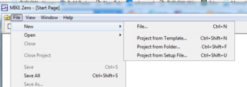
- Open the MIKE Zero program
- From the MIKE Zero shell select File >> New >> File
- On the MIKE Zero button select MIKE Zero Toolbox (.mzt). Click OK.
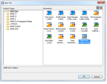
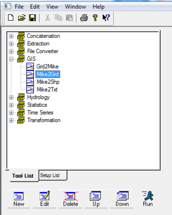
- Under the GIS dropdown, double click MIKE2GRD
- Work through the steps being careful to specify an appropriate projection
- Before clicking Finish, ensure you have clicked Execute to run the conversion
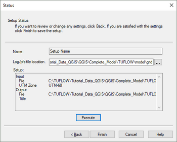
- This should produce an ascii file that can be directly read by TUFLOW


Unlike TUFLOW, the grid cell size of the model in MIKE is determined directly by the input grid file. For more discussion on grid cell size and the differences in how MIKE and TUFLOW handle the underlying terrain please see the Discussion Section at the bottom of the page.
Note: After grid conversion, it is important to perform checks that the ascii grid has been converted properly. This is best done in your preferred GIS package.
Converting Manning's
Follow the same steps as converting terrain to convert the manning’s grid using the Mike Zero Toolbox. It is important to identify the manning’s value type (M or n) so that it can be correctly read into TUFLOW. This can be done by viewing the .dfs2 grid in Mike Zero following the steps below:
- Open the MIKE Zero program
- Open the .dfs2 file through Open (or drag and drop)
- From the toolbar select Edit >> Items…
- The value should be listed in Type
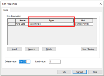

More information on reading in manning’s grids into TUFLOW is provided in the TUFLOW Manual.
Model Domain
The model domain can be manually set by viewing the terrain and manning’s data in your preferred GIS program, or set using the Read Grid Location command.
! Set model domain
Read Grid Location == ..\model\grid\example_grid.asc
Grid rotation in the MIKE model can be determined using the following steps:
- Open the MIKE Zero program
- Open the .dfs2 elevation grid through Open (or drag and drop)
- From the toolbar select Edit >> Custom Blocks…
- The first element value is the rotation value (orientation at origin relative to true north)
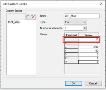

More information on setting the model domain extent and rotation in TUFLOW is provided in the TUFLOW Manual.
TUFLOW Code Layer
The user can manually set the TUFLOW code layer by viewing the terrain data through their preferred GIS program. MIKE also uses a process of defining active cells by specifying a ‘Land’ elevation value. A ‘Land’ elevation value is defined in the .dsf2 grid file that specifies a value at which elevations equal to or greater than this value are considered ‘Land’ and will not be subject to possible wetting and drying. This value could be used as a guidance for producing a TUFLOW code layer. The 'Land' value can be found in Custom Blocks, the same location as grid rotation. Following the same steps as above in determining rotation, the 'Land' value can be determined, this time looking at the fourth element value
Note: A downfall of this method in MIKE, is that elevations in the .dfs2 grid may have been manually modified such that the area outside the flood extent has a constant ‘Land’ elevation. Inspection of the terrain data before use is highly recommended.
Creating a TUFLOW Boundary Control File from MIKE21 and MIKE Flood
This section discusses how to extract data from a MIKE model to populate the TUFLOW Boundary Control file (TBC). The TBC file defines the:
- Downstream boundary
- Inflow locations
- 1D/2D linking
Upstream and Downstream Boundaries
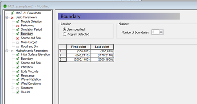
The location of upstream and downstream boundaries can be found in the MIKE21 control file (.m21) in the Basic Parameters >> Boundary tab. The location of the boundaries are specified as a line object using the start and end vertices in the local (j, k) coordinate system. These are required to be converted to absolute coordinates so an identical boundary location can be digitised in TUFLOW. This can be done in MS Excel using the following steps:
- Identify boundary locations
- Open the MIKE Zero program
- Open the .m21 file through Open (or drag and drop)
- Navigate to the Basic Parameters >> Boundary tab
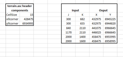
- In excel convert these (j,k) coordinates to an absolute reference (X, Y)
- From the converted terrain ascii grid (Section 2.1), copy Cellsize, xllcorner, and yllcorner values from the grid header into Excel
- Copy your (j, k) values into Excel
- Use the following formulas to convert your (j, k) values to (X, Y)
- X = xllcorner + j * cellsize
- Y = yllcorner + k * cellsize


The type of the boundary is defined in the Hydrodynamic Parameters >> Boundary tab. This tab specifies whether the boundary is ‘Flux’ (QT), ‘Level’ (HT), or ‘Rating Curve’ (HQ), as well as whether the data is a time series (type 0 data file) or constant.
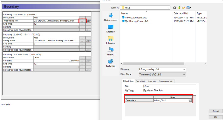
The name of the boundary can be found following the below steps:
- Click the ‘…’ button to browse
- Viewing Item which corresponds to the boundary name

The Upstream boundary can be digitised in TUFLOW as a 2d_bc (type ‘HT’), or as a 2d_SA polygon. For more discussion on selecting an appropriate upstream boundary type, please see the Discussion Section at the bottom of the page.
Source Boundaries
The location of source boundaries can be found in the MIKE21 control file (.m21) in the Basic Parameters >> Source and Sink tab. The location of the boundaries are specified as a point object using the local (j, k) coordinate system. These are required to be converted to absolute coordinates so an identical boundary location can be digitised in TUFLOW. The conversion process can be undertaken using identical steps as performed with converting upstream and downstream boundaries.
It is recommended that the source boundary point from MIKE be converted to a 2d_SA polygon in TUFLOW. The 2d_SA polygon should be enlarged to encompass a larger region such that it is able to apply flow to more than one cell. This is considered to give a more stable and accurate representation of flow distribution to the model. More information on how 2d_SA polygons distributes flow can be found in the TUFLOW Manual.
The name of the boundary can be found from Hydrodynamic Parameters >> Source and Sink tab.
1D/2D Linking Boundaries
The location of the 1D / 2D boundaries can be found in the MIKE Flood control file (.couple) under the Link Definitions tab. The (X, Y) coordinates specify the vertices of a polyline that can be digitised in TUFLOW using either ‘SX’ or ‘HX’ connections.
More information on 1D/2D linking in TUFLOW can be found in the TUFLOW Manual.
Creating a Boundary Control Database from MIKE
A Boundary Control Database (bc_dbase) consists of the values (time series or constant value) and the linking boundary names. The boundary names, constant values, and data source for time series, can be obtained from the steps outlined in:
- Section 3 - Creating a TUFLOW Boundary Control File from MIKE21 and MIKE Flood
- Section 5.2 – 1D Boundaries
Converting DSF0 time series
Time series values need to be extracted from MIKE time series files (.dfs0). This can be done following the steps below:
- Open the MIKE Zero program
- Open the .dfs0 file through Open (or drag and drop)
- Select File >> Export to ASCII…
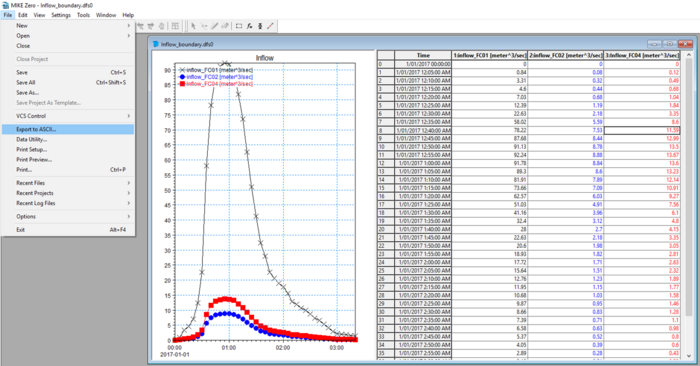
- This will export the time series data to a text based format

The time series will need to be formatted so that the time column units are in hours. This can be done in MS Excel or equivalent. More information on setting up inflow boundaries can be found in the TUFLOW Manual.
Creating an Estry Control File from MIKE11
This section discusses how to extract data from a MIKE11 model to create an Estry Control File (ECF). An ECF file defines the:
- 1D network – Channels, structures
- 1D cross sections
- 1D boundaries
- 1D run settings
1D Network Conversion (xsGenerator.exe Utility)
To make the conversion of the MIKE11 1D network easier, the xsGenerator utility has been built to automate the bulk of the conversion. The xsGenerator.exe utility is freely available to download from the TUFLOW website.
To undertake the automation, a number of files will be required as inputs:
- Projection.mif (or Header.mif)
- The MIKE11 .nwk11
- The MIKE11 .bd11
- The MIKE11 exported <Cross_sections>.txt
At this time, the utility is only able to output to .mif and this would need to be converted to .shp if required.
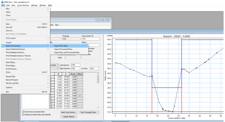
Cross sections from MIKE11 can be exported by following the steps below:
- Open MIKE Zero
- Open the .xns11 through Open (or drag and drop)
- Select File >> Export All Sections >> Export Raw Data…
- Save the cross sections out as a .txt file

The final step is to convert the network data into TUFLOW format. This can be done by creating a batch file to run the utility. Below is an example of the arguments used to convert the MIKE11 network. Documentation on the utility can be found on the xsGenerator wiki page
xsGenerator.exe -N -m11 Projection.mif XS_example.txt HD_example.hd11 M11_example.nwk11.
After the conversion is complete it is important to check the output. Some key areas to check are:
- The 1d_nwk.mif file appears to have created channels at reasonable locations
- The 1d_nwk.mif ‘Type’ attribute is correct (currently the utility will assign all channels to type ‘S’ (see below for checking for culverts in MIKE11)
- The 1d_xs.mif file appears to be at reasonable locations (if the cross sections in MIKE11 didn’t have X,Y coordinates, then the equivalent 1d_xs cross sections can look strange)
- TUFLOW also does not require cross sections at embedded 1D/2D culverts, therefore cross sections at these locations can be deleted
- The created cross section .csv files are reasonable (geometry and manning’s values)
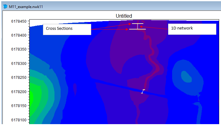
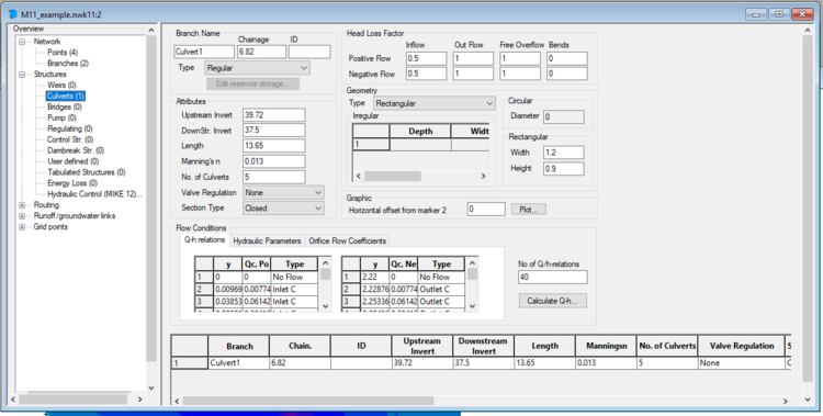
The following steps describe how to inspect channel locations and types in MIKE11 for the purpose of checking the utility output:
- Open MIKE Zero
- Open the .nwk11 file through Open (or drag and drop)
- This will display the network spatially
- To view the details, select View >> Tabular View…
- From this screen you view information on Structures that you can use to populate attributes for any structures in the 1d_nwk TUFLOW layer


1D Boundaries
The following steps will help identify the types of 1D boundaries and the attributes used in MIKE11 for transfer to TUFLOW:
- Open MIKE Zero
- Open the .bnd11 file through Open (or drag and drop)
- This will display all 1D boundaries
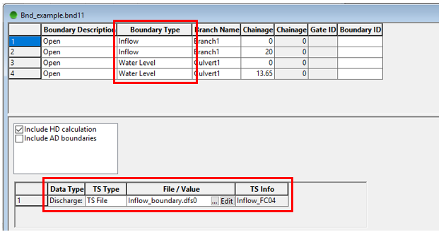

Identifying the boundary types and values is as simple as reading the Boundary Type, TS Type, and File/Value. The only thing to be careful of is that 1D/2D linking boundaries are usually specified as Water Level and won’t need to be transferred across (1D/2D linking conversion has already been discussed in Section 3.3 - 1D/2D Linking Boundaries).
1D Run Settings
The 1D run settings can be obtained from the .sim11 file. However it is recommended that appropriate run settings for TUFLOW be applied and direct copying from MIKE is not necessary.
Creating a TUFLOW Control File from MIKE21
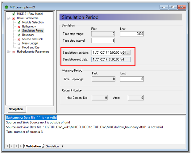
The primary run setting to extract from the MIKE21 model is the duration of the simulation. This can be done by following the steps below:
- Open MIKE Zero
- Open the .m21 file through Open (or drag and drop)
- Select the tab Basic Parameters >> Simulation Period
- You can obtain the start and end dates from this tab which need to be converted to hours for TUFLOW (in the screenshot below, the simulation duration is 3 hours)

The 2D timestep should be set to an appropriate TUFLOW interval and not be copied directly from the MIKE21 model. It also up to the user to consider output types and time series Plot Output (PO) locations. More information on appropriate timestep intervals and map output types can be found in the TUFLOW Manual.
Discussion
The below are a series of links to discussions that may interest anyone converting a MIKE Flood model to TUFLOW.
- MIKE–TUFLOW discussion on how the models interpret the underlying terrain (coming soon)
- MIKE–TUFLOW result difference discussion (coming soon)
- Discussion on QT and SA boundary selection (coming soon)