XPSWMM to TUFLOW-SWMM: Difference between revisions
| Line 505: | Line 505: | ||
'''Note:''' For this demonstration, all commands will reference the datasets in the provided conversion model. Please update these references with the filenames sued in your model.<br> |
'''Note:''' For this demonstration, all commands will reference the datasets in the provided conversion model. Please update these references with the filenames sued in your model.<br> |
||
<br> |
<br> |
||
=== Optional: Format TUFLOW Control Files === |
|||
In the process of converting a model, the <u>[[Convert_TUFLOW_Model_GIS_Format |Convert TUFLOW Model GIS Format]]</u> processing tool adds commands to the TUFLOW control files created by XPSWMM. While these control files contain most of the essential commands, they typically lack sufficient information to enable the mode to run smoothly. |
|||
In the sections above, we removed unnecessary commands from the TUFLOW control files and introduced additional commands to ensure the TUFLOW SWMM model runs smoothly. In this section, we will format and organize the TUFLOW control files to enhance readability, thereby improving the overall functionality of the model. This can be done by: |
|||
:* Using relative file paths to specify the location of various files and layers in the model. |
|||
:* Including a title at the beginning of each control file. For example, <font color="green"><tt>! TUFLOW CONTROL FILE (.TCF) defines the model simulation parameters and directs input from other data sources</tt></font>. |
|||
:* Adding headings to sections of the control file. For example, <font color="green"><tt>! MODEL INITIALIZATION</tt></font> could be used as a header for the commands required to initialize the TUFLOW SWMM model. |
|||
:* Utilizing comments to explain the purpose of commands. For example, <font color="blue"><tt>Spatial Database </tt></font> <font color="red"><tt>== </tt></font> <font color="black"><tt> ..\model\gis\1D2D_Urban_001.gpkg </tt></font> <font color="green"><tt> ! Specify the location of the GeoPackage Spatial Database</tt></font>.<br> |
|||
=== Clean TUFLOW Control Files === |
=== Clean TUFLOW Control Files === |
||
| Line 576: | Line 565: | ||
<li> |
<li> |
||
</ol> |
</ol> |
||
Additionally, these files are often not neatly structured. To ensure a functional and easily readable mode, it is recommended to 'clean up' the TUFLOW control files. This can be done by: |
|||
:* Adding in commands required to execute the model. For example, <font color="blue"><tt>Solution Scheme </tt></font> <font color="red"><tt>== </tt></font> <font color="black"><tt> HPC </tt></font> <font color="green"><tt> ! Heavily Parallelised Compute, uses adaptive timestepping</tt></font>.<br> |
|||
:* Removing unnecessary commands. |
|||
:* Using relative file paths to specify the location of various files and layers in the model. |
|||
:* Including a title at the beginning of each control file. For example, <font color="green"><tt>! TUFLOW CONTROL FILE (.TCF) defines the model simulation parameters and directs input from other data sources</tt></font>. |
|||
:* Adding headings to sections of the control file. For example, <font color="green"><tt>! MODEL INITIALIZATION</tt></font> could be used as a header for the commands required to initialize the TUFLOW SWMM model. |
|||
:* Using comments to explain the purpose of commands. For example, <font color="blue"><tt>Spatial Database </tt></font> <font color="red"><tt>== </tt></font> <font color="black"><tt> ..\model\gis\1D2D_Urban_001.gpkg </tt></font> <font color="green"><tt> ! Specify the location of the GeoPackage Spatial Database</tt></font>.<br> |
|||
<br> |
|||
The process below demonstrates how to clean up a TCF, using the provided model conversion dataset. |
|||
<ol> |
|||
<li> In Windows File Explorer, navigate to the '''TUFLOW\runs''' folder and open the TCF into a Text Editor (Notepad++ is recommended). |
|||
<li> Add control file title and section headings: <br> |
|||
<font color="green"><tt>! TUFLOW CONTROL FILE (.TCF) defines the model simulation parameters and directs input from other data sources<br> |
|||
! MODEL INITIALIZATION <br> |
|||
! SOLUTION SCHEME <br> |
|||
! MODEL INPUTS <br> |
|||
! TIME CONTROL <br> |
|||
! OUTPUT FOLDERS <br> |
|||
! OUTPUT SETTINGS <br> |
|||
! TIME SERIES PLOT OUTPUT</tt></font> |
|||
<li> Organize the commands into these section headings. <br> |
|||
<font color="green"><tt>! MODEL INITIALIZATION</tt></font><br> |
|||
<font color="blue"><tt>Spatial Database </tt></font> <font color="red"><tt>== </tt></font> <font color="black"><tt> ..\model\gis\1D2D_Urban_001.gpkg </tt></font> <br> |
|||
<font color="blue"><tt>GPKG Projection </tt></font> <font color="red"><tt>== </tt></font> <font color="black"><tt> ??? </tt></font> <br> |
|||
<font color="blue"><tt>TIF Projection </tt></font> <font color="red"><tt>== </tt></font> <font color="black"><tt> ..\model\grid\1D2D_Urban_Grid.tif </tt></font> <br> |
|||
<font color="green"><tt>! MODEL INPUTS</tt></font><br> |
|||
<font color="blue"><tt>Geometry Control File </tt></font> <font color="red"><tt>== </tt></font> <font color="black"><tt> ..\model\1D2D_Urban_001.tgc </tt></font> <br> |
|||
<font color="blue"><tt>BC Control File </tt></font> <font color="red"><tt>== </tt></font> <font color="black"><tt> ..\model\1D2D_Urban_001.tbc </tt></font> <br> |
|||
<font color="blue"><tt>BC Database </tt></font> <font color="red"><tt>== </tt></font> <font color="black"><tt> ..\bc_dbase\1D2D_Urban_001_2d_bc_db.csv </tt></font> <br> |
|||
<font color="blue"><tt>Read Materials File </tt></font> <font color="red"><tt>== </tt></font> <font color="black"><tt> ..\model\1D2D_Urban_001_Mat.csv </tt></font> <br> |
|||
<font color="blue"><tt>Read Soils File </tt></font> <font color="red"><tt>== </tt></font> <font color="black"><tt> ..\model\1D2D_Urban_001.tsoilf </tt></font> <br> |
|||
<font color="green"><tt>! TIME CONTROL</tt></font><br> |
|||
<font color="blue"><tt>Timestep </tt></font> <font color="red"><tt>== </tt></font> <font color="black"><tt> 1.000000 </tt></font> <br> |
|||
<font color="green"><tt>! OUTPUT SETTINGS</tt></font><br> |
|||
<font color="blue"><tt>Map Output Data Types </tt></font> <font color="red"><tt>== </tt></font> <font color="black"><tt> q V d h Z0 </tt></font> <br> |
|||
<font color="blue"><tt>Map Output Interval (s) </tt></font> <font color="red"><tt>== </tt></font> <font color="black"><tt> 60.000000 </tt></font> <br> |
|||
<font color="green"><tt>! TIME SERIES PLOT OUTPUT</tt></font><br> |
|||
<font color="blue"><tt>Read GIS PO </tt></font> <font color="red"><tt>== </tt></font> <font color="black"><tt> 1D2D_Urban_001_2d_po_P </tt></font> <br> |
|||
<font color="blue"><tt>Read GIS PO </tt></font> <font color="red"><tt>== </tt></font> <font color="black"><tt> 1D2D_Urban_001_2d_po_L </tt></font> <br> |
|||
<font color="blue"><tt>Time Series Output Interval (s) </tt></font> <font color="red"><tt>== </tt></font> <font color="black"><tt> 60.000000 </tt></font> <br> |
|||
<li> In the 'Model Initialization' and 'Solution Scheme' sections, add in the commands required to run the TUFLOW model: <br> |
|||
<font color="green"><tt>! MODEL INITIALIZATION</tt></font><br> |
|||
<font color="blue"><tt>Tutorial Model </tt></font> <font color="red"><tt>== </tt></font> <font color="black"><tt> ON </tt></font> <br> |
|||
<font color="blue"><tt>GIS Format </tt></font> <font color="red"><tt>== </tt></font> <font color="blue"><tt> GPKG </tt></font> <br> |
|||
<font color="green"><tt>! SOLUTION SCHEME</tt></font><br> |
|||
<font color="blue"><tt>Solution Scheme </tt></font> <font color="red"><tt>== </tt></font> <font color="blue"><tt> HPC </tt></font> <br> |
|||
<font color="blue"><tt>Hardware </tt></font> <font color="red"><tt>== </tt></font> <font color="blue"><tt> GPU </tt></font> <br> |
|||
<li> Set the start and end time of the model:<br> |
|||
<font color="green"><tt>! TIME CONTROL</tt></font><br> |
|||
<font color="blue"><tt>Start Time </tt></font> <font color="red"><tt>== </tt></font> <font color="black"><tt> 0</tt></font> <br> |
|||
<font color="blue"><tt>End Time </tt></font> <font color="red"><tt>== </tt></font> <font color="black"><tt> 3 </tt></font> <br> |
|||
<li> Set the model output folders:<br> |
|||
<font color="green"><tt>! OUTPUT FOLDERS</tt></font><br> |
|||
<font color="blue"><tt>Log Folder </tt></font> <font color="red"><tt>== </tt></font> <font color="black"><tt> log </tt></font> <br> |
|||
<font color="blue"><tt>Output Folder </tt></font> <font color="red"><tt>== </tt></font> <font color="black"><tt> ..\results\ </tt></font> <br> |
|||
<font color="blue"><tt>Write Check Files </tt></font> <font color="red"><tt>== </tt></font> <font color="black"><tt> ..\check\ </tt></font> <br> |
|||
<li> Add the following commands to the 'Output Settings' section:<br> |
|||
<font color="blue"><tt>Map Output Format </tt></font> <font color="red"><tt>== </tt></font> <font color="blue"><tt> XMDF TIF </tt></font> <br> |
|||
<font color="blue"><tt>TIF Map Output Interval </tt></font> <font color="red"><tt>== </tt></font> <font color="black"><tt> 0 </tt></font> <br> |
|||
<li> Add comments to explain the commands. |
|||
<li> Remove all commands not included in the headings above, they are unnecessary for a TUFLOW SWMM model. |
|||
<li> If using the provided model conversion dataset, the final TCF should look like this: |
|||
<br><br> |
|||
[[File:XPSWMM_to_TUFLOW_clean_up_TCF_01b.png]] |
|||
<br> |
|||
</ol> |
|||
<br> |
|||
=== TUFLOW Control File (TCF) === |
=== TUFLOW Control File (TCF) === |
||
| Line 660: | Line 580: | ||
<ol> |
<ol> |
||
<li> In Windows File Explorer, navigate to the '''TUFLOW\model''' folder and create a new blank text file with the extension .tscf. |
<li> In Windows File Explorer, navigate to the '''TUFLOW\model''' folder and create a new blank text file with the extension .tscf. |
||
<li> Open the TSCF into a Text Editor (Notepad++ is recommended) and add the following commands |
<li> Open the TSCF into a Text Editor (Notepad++ is recommended) and add the following commands.<br> |
||
<font color="blue"><tt>Read SWMM </tt></font> <font color="red"><tt>== </tt></font> <font color="black"><tt>..\swmm\1D2D_Urban_HDR_001.inp </tt></font> <font color="green"><tt> ! 1D SWMM Pipe Network input file</tt></font><br> |
<font color="blue"><tt>Read SWMM </tt></font> <font color="red"><tt>== </tt></font> <font color="black"><tt>..\swmm\1D2D_Urban_HDR_001.inp </tt></font> <font color="green"><tt> ! 1D SWMM Pipe Network input file</tt></font><br> |
||
<font color="blue"><tt>Read SWMM </tt></font> <font color="red"><tt>== </tt></font> <font color="black"><tt>..\swmm\1D2D_Urban_RNF_001.inp </tt></font> <font color="green"><tt> ! 1D SWMM Hydrology input file</tt></font><br> |
<font color="blue"><tt>Read SWMM </tt></font> <font color="red"><tt>== </tt></font> <font color="black"><tt>..\swmm\1D2D_Urban_RNF_001.inp </tt></font> <font color="green"><tt> ! 1D SWMM Hydrology input file</tt></font><br> |
||
| Line 674: | Line 594: | ||
<ol> |
<ol> |
||
<li> In Windows File Explorer, navigate to the '''TUFLOW\model''' folder and open the TBC into a text editor (Notepad++ is recommended). |
<li> In Windows File Explorer, navigate to the '''TUFLOW\model''' folder and open the TBC into a text editor (Notepad++ is recommended). |
||
<li> Remove the reference to the 2d_bc points layer. This layer was removed from the model GeoPackage in the <u>[[#Export_1D_EPA_SWMM_Pipe_Network_Data_from_XPSWMM |Export 1D EPA SWMM Pipe Network Data from XPSWMM]]</u> section. |
|||
<li> Add the following command to reference the link between the 1D SWMM culverts and the 2D TUFLOW domain.<br> |
|||
<li> The TBC should reference the 2D boundary condition layer and the 1D/2D connection layer. In this case, they are both included in the 2d_bc connections layer. <br> |
|||
<font color="blue"><tt>Read GIS BC </tt></font> <font color="red"><tt>== </tt></font> <font color="black"><tt>2d_bc_Culvert_Connections_001_L </tt></font> <font color="green"><tt> ! Links 1D SWMM culverts to the 2D TUFLOW domain</tt></font><br> |
|||
<font color="blue"><tt>Read GIS BC </tt></font> <font color="red"><tt>== </tt></font> <font color="black"><tt>1D2D_Urban_001_2d_bc_L </tt></font> <font color="green"><tt> ! Reads in 2D boundaries and links 1D SWMM culverts to the 2D TUFLOW domain</tt></font><br> |
|||
<br> |
<br> |
||
'''<font color="red">Video</font>''' |
'''<font color="red">Video</font>''' |
||
| Line 687: | Line 608: | ||
:* Bed material type or flow resistance value. |
:* Bed material type or flow resistance value. |
||
<br> |
<br> |
||
The TGC requires no updates; however, it is recommended to review the TGC before running the simulation to ensure all commands are correct. |
|||
<br><br> |
<br><br> |
||
=== TUFLOW Control File (TCF) === |
|||
The TCF file references all the control files, specifies time and output controls.<br> |
|||
In the <u>[[#Convert_XPSWMM_Model_to_Recommended_TUFLOW_Structure | Convert XPSWMM Model to Recommended TUFLOW Structure]]</u> section, the <u>[[Convert_TUFLOW_Model_GIS_Format |Convert TUFLOW Model GIS Format]]</u> processing tool utilizes the TUFLOW control files generated by XPSWMM to construct the TUFLOW SWMM model control files. During this process, the tool updates the commands within the TUFLOW control files to align with the requirements of a TUFLOW SWMM model. However, since the original control files were intended for use with XPSWMM, they lack the commands required to execute a TUFLOW simulation. Additionally, these files often contain unnecessary and/or outdated commands.<br> |
|||
In the section above, the TBC was edited to reflect the model updates implemented during the conversion process, while no updates were necessary for the TGC. However, the TCF requires updating to ensure the TUFLOW SWMM model runs smoothly. |
|||
<ol> |
|||
<li> Remove or comment out the commands listed below. |
|||
{| |
|||
|style="width: 50%"| <font color="blue"><tt>Check MI Save Date </tt></font> <font color="red"><tt>== </tt></font> |
|||
|<font color="blue"><tt>Mass Balance Output Interval (s) </tt></font> <font color="red"><tt>== </tt></font> |
|||
|- |
|||
|<font color="blue"><tt>MI Projection </tt></font> <font color="red"><tt>== </tt></font> |
|||
|<font color="blue"><tt>CSV Time </tt></font> <font color="red"><tt>== </tt></font> |
|||
|- |
|||
|<font color="blue"><tt>MI Projection Check </tt></font> <font color="red"><tt>== </tt></font> |
|||
|<font color="blue"><tt>Viscosity Formulation </tt></font> <font color="red"><tt>== </tt></font> |
|||
|- |
|||
|<font color="blue"><tt>Timestep (s) </tt></font> <font color="red"><tt>== </tt></font> |
|||
|<font color="blue"><tt>Viscosity Coefficient </tt></font> <font color="red"><tt>== </tt></font> |
|||
|- |
|||
|<font color="blue"><tt>Cell Wet/Dry Depth </tt></font> <font color="red"><tt>== </tt></font> |
|||
|<font color="blue"><tt>SX ZC Check </tt></font> <font color="red"><tt>== </tt></font> |
|||
|- |
|||
|<font color="blue"><tt>Read GIS XP Nodes </tt></font> <font color="red"><tt>== </tt></font> |
|||
|<font color="blue"><tt>SX Storage Approach </tt></font> <font color="red"><tt>== </tt></font> |
|||
|- |
|||
|<font color="blue"><tt>Simulations Log Folder </tt></font> <font color="red"><tt>== </tt></font> |
|||
|<font color="blue"><tt>HX ZC Check </tt></font> <font color="red"><tt>== </tt></font> |
|||
|- |
|||
|<font color="blue"><tt>Store Maximums and Minimums </tt></font> <font color="red"><tt>== </tt></font> |
|||
|<font color="blue"><tt>Mass Balance Corrector </tt></font> <font color="red"><tt>== </tt></font> |
|||
|- |
|||
|<font color="blue"><tt>Mass Balance Output </tt></font> <font color="red"><tt>== </tt></font> |
|||
|} |
|||
<li> Make the following updates: |
|||
{|class="wikitable" |
|||
! Original Command |
|||
! Updated Command |
|||
|- |
|||
|<font color="blue"><tt>GPKG Projection </tt></font> <font color="red"><tt>== </tt></font> <font color="black"><tt>1D2D_Urban_001_proj</tt></font> |
|||
|<font color="blue"><tt>GPKG Projection </tt></font> <font color="red"><tt>== </tt></font> <font color="black"><tt>??</tt></font> |
|||
|- |
|||
|<font color="blue"><tt>Write Check Files </tt></font> <font color="red"><tt>== </tt></font> <font color="black"><tt>OFF</tt></font> |
|||
|<font color="blue"><tt>Write Check Files </tt></font> <font color="red"><tt>== </tt></font> <font color="black"><tt>..\check\</tt></font> |
|||
|- |
|||
|<font color="blue"><tt>Output Folder </tt></font> <font color="red"><tt>== </tt></font> <font color="black"><tt>..\results\Output </tt></font> |
|||
|<font color="blue"><tt>Output Folder </tt></font> <font color="red"><tt>== </tt></font> <font color="black"><tt>..\results\</tt></font> |
|||
|- |
|||
|<font color="blue"><tt>Log Folder </tt></font> <font color="red"><tt>== </tt></font> <font color="black"><tt>log\Log </tt></font> |
|||
|<font color="blue"><tt>Output Folder </tt></font> <font color="red"><tt>== </tt></font> <font color="blue"><tt>log</tt></font> |
|||
|- |
|||
|<font color="blue"><tt>Map Output Data Types </tt></font> <font color="red"><tt>== </tt></font> <font color="black"><tt>qVdhZ0 </tt></font> |
|||
|<font color="blue"><tt>Map Output Data Types </tt></font> <font color="red"><tt>== </tt></font> <font color="black"><tt>q V d h Z0</tt></font> |
|||
|- |
|||
|<font color="blue"><tt>Map Output Format </tt></font> <font color="red"><tt>== </tt></font> <font color="blue"><tt>XMDF </tt></font> |
|||
|<font color="blue"><tt>Map Output Format </tt></font> <font color="red"><tt>== </tt></font> <font color="blue"><tt>XMDF TIF</tt></font> |
|||
|} |
|||
<li> Add the following commands:<br> |
|||
<font color="blue"><tt>Tutorial Model </tt></font> <font color="red"><tt>== </tt></font> <font color="blue"><tt>ON </tt></font> <font color="green"><tt> ! Required command to run this tutorial model licence free</tt></font><br> |
|||
<font color="blue"><tt>GIS Format </tt></font> <font color="red"><tt>== </tt></font> <font color="blue"><tt>GPKG </tt></font> <font color="green"><tt> ! Specify GPKG as the output format for all GIS files</tt></font><br> |
|||
<font color="blue"><tt>Solution Scheme </tt></font> <font color="red"><tt>== </tt></font> <font color="blue"><tt>HPC </tt></font> <font color="green"><tt> ! Heavily Parallelised Compute, uses adaptive timestepping</tt></font><br> |
|||
<font color="blue"><tt>Hardware </tt></font> <font color="red"><tt>== </tt></font> <font color="blue"><tt>CPU </tt></font> <font color="green"><tt> ! Replace with "Hardware == GPU" if GPU available </tt></font><br> |
|||
<font color="blue"><tt>Start Time </tt></font> <font color="red"><tt>== </tt></font> <font color="black"><tt>0 </tt></font> <font color="green"><tt> ! Specifies the simulation start time (0 hours) </tt></font><br> |
|||
<font color="blue"><tt>End Time </tt></font> <font color="red"><tt>== </tt></font> <font color="black"><tt>3 </tt></font> <font color="green"><tt> ! Specifies the simulation end time (3 hours)</tt></font><br> |
|||
<li> Add the following command to reference the TUFLOW SWMM Control File (TSCF):<br> |
|||
<font color="blue"><tt>SWMM Control File </tt></font> <font color="red"><tt>== </tt></font> <font color="black"><tt>..\model\1D2D_Urban_001.tscf</tt></font> |
|||
</ol> |
|||
=== Optional: Format TUFLOW Control Files === |
|||
In the sections above, we removed unnecessary commands from the TUFLOW control files and introduced additional commands to ensure the TUFLOW SWMM model runs smoothly. In this section, we will format and organize the TUFLOW control files to enhance readability, thereby improving the overall functionality of the model. This can be done by: |
|||
:* Using relative file paths to specify the location of various files and layers in the model. |
|||
:* Including a title at the beginning of each control file. For example, <font color="green"><tt>! TUFLOW CONTROL FILE (.TCF) defines the model simulation parameters and directs input from other data sources</tt></font>. |
|||
:* Adding headings to sections of the control file. For example, <font color="green"><tt>! MODEL INITIALIZATION</tt></font> could be used as a header for the commands required to initialize the TUFLOW SWMM model. |
|||
:* Utilizing comments to explain the purpose of commands. For example, <font color="blue"><tt>Spatial Database </tt></font> <font color="red"><tt>== </tt></font> <font color="black"><tt> ..\model\gis\1D2D_Urban_001.gpkg </tt></font> <font color="green"><tt> ! Specify the location of the GeoPackage Spatial Database</tt></font>.<br> |
|||
<br> |
|||
If using the provided model conversion dataset, the final Control files should look like this:<br> |
|||
'''<font color="red"> insert images when dataset finalised </font>''' |
|||
<br> |
|||
=Converted Dataset= |
=Converted Dataset= |
||
Revision as of 15:29, 14 February 2024
Page Under Construction - Expected Finalization date: 23 February 2024
Introduction
This Wiki page outlines recommended steps for conversion of an XPSWMM model to TUFLOW.
XPSWMM is a flood and urban stormwater drainage modeling software developed by Autodesk (previously Innovyze and XP Solutions). The XPSWMM solution uses EPA SWMM for its 1D calculations, dynamically linked to TUFLOW for its 2D calculations. The software functions within a custom build Graphical User interface (GUI). During simulation, XPSWMM calls a TUFLOW dynamic library for the 2D calculations. As XPSWMM uses TUFLOW for its 2D engine, XPSWMM and TUFLOW use the same 2D solution and will achieve identical results if configured in a like-for-like way.
Common user feedback suggests the XPSWMM GUI is useful for simple modeling projects; however, it can become cumbersome and inefficient in workflow when dealing with larger datasets and/or a large volume of different scenario and event simulations. In response to requests from USA XPSWMM users who want to convert XPSWMM models into a native TUFLOW format, TUFLOW linkage with 1D EPA Storm Water Management Model (SWMM) was added as a supported feature in TUFLOW 2023-03-AD release. The modeling workflow in TUFLOW differs from XPSWMM, as TUFLOW modeling is integrated with QGIS (Geographical Information System) GIS software. This GIS integration is well-suited for working with larger datasets. Additionally, the structural design associated with TUFLOW modeling makes its general workflow extremely efficient, particularly for the automated management of multiple scenarios and events.
If you are building a TUFLOW SWMM model from scratch, not from XPSWMM, please refer to the TUFLOW SWMM Tutorials. Tutorials are provided for the following topics:
- TUFLOW SWMM Module 1 - 1D SWMM Culverts
- TUFLOW SWMM Module 2 - 1D SWMM Pipe Network / 2D TUFLOW Direct Rainfall Hydrology
- TUFLOW SWMM Module 3 - 1D SWMM Pipe Network / 1D SWMM Urban Hydrology
- TUFLOW SWMM Module 4 - 1D SWMM Pipe Network / 1D SWMM Urban Hydrology: Executing multiple different event simulations from a single model control file.
TUFLOW Licensing / XPSWMM Discount
If you are an existing / or past XPSWMM perpetual license owner who would like to purchase a TUFLOW license, please contact sales@tuflow.com. You may be eligible for an XPSWMM / TUFLOW discount in recognition of past royalties Autodesk paid TUFLOW when you purchased an XPSWMM perpetual license.
XPSWMM to TUFLOW Model Conversion
Dataset Download
The XPSWMM model used for this model conversion demonstration is available for download here: XPSWMM to TUFLOW Model Conversion Dataset. A copy of the completed converted model can be downloaded at the end of the page.
If you are using this example conversion dataset, please rerun the XPSWMM model before beginning the conversion process. This will generate the XPSWMM TUFLOW files and establish the correct file paths within them, aligning with the location where you have saved the dataset on your computer.
Two Dimensional (2D) Model Elements
XPSWMM writes TUFLOW model files when it pre-processes the model inputs defined in its GUI (prior to the hydraulic calculations). Using default settings, XPSWMM typically writes the TUFLOW files to the 2D\Data folder.
The following sections explain how 2D data can be exported from XPSWMM and/or reconfigured into a format that is more standard of a TUFLOW model. The conversion has been summarized into three steps:
- Obtain Digital Terrain Model (DTM) dataset for TUFLOW model.
- Use TUFLOW's Processing Tool to configure the XPSWMM written TUFLOW files into a standard TUFLOW folder structure and GIS database format.
- Manual optional changes to the TUFLOW control files.
Digital Terrain Model (DTM) Data
XPSWMM reads its 2D DTM data in one of two ways:
- The DTM data can be directly specified in the '2D Model Settings', or
- The DTM data can be internally processed by XPSWMM using its terrain tools and DTM builder.
Depending which method is applied to your XPSWMM model, the steps required to convert the model to TUFLOW will vary.
Let's review what method is used:
- Open your existing model in XPSWMM.
- In the top dropdown menu options, navigate to Configuration > Job control > 2D Model Settings. This will open a dialog.
- Under '2D Hydraulics Job Control', select 'Surface & Sampling'.
- Review the options in the 'Surface' section:
- If 'Use DTM' is selected: Continue to the section below (XPSWMM DTM Preprocessing) and complete the steps.
- If 'Use Grid File for Topography' is selected and a 'Grid file' is specified: Go to the Convert XPSWMM Model to Recommended TUFLOW Structure section. The steps outlined in the 'XPSWMM DTM Preprocessing' section can be skipped.
XPSWMM DTM Preprocessing
If 'Use DTM' was selected, XPSWMM pre-processes its Digital Terrain Model (DTM) into a binary XPTIN elevation dataset for inclusion in the TUFLOW model. XPTIN is a propriety format that can't readily be used in GIS software. For this reason, the following section outlines how to obtain a DTM dataset in a GIS friendly form.
- Note: If 'Use DTM' was selected, follow the steps below. Otherwise, do not complete these steps; continue to the Convert XPSWMM Model to Recommended TUFLOW Structure section.
XPSWMM provides two options for preprocessing the DTM to be used in the TUFLOW model, both options are outlined below. As 'Option 1' is straightforward and 'Option 2' is more involved, 'Option 2' is demonstrated in the video below.
- Option 1 (recommended) - Use Original Source Elevation Data Imported to XPSWMM:
- Locate the original 'Grid' file (.asc or .flt/.hdr format). Save it to the folder where XPSWMM writes the .tcf during its simulation preprocessing. By default, this is the 2D\Data folder.
If this folder does not exist, either:- The XPSWMM model has not run, so the TUFLOW control files have not been created by XPSWMM. Run the XPSWMM model (go to Analyze > Solve... in top dropdown menu options).
- Non-default output settings have been specified in XPSWMM. To determine the output location, in the top dropdown menu options, go to Configuration > Job Control > 2D Model Settings > Folder Options. Ensure the following 'Folder Locations' are selected:
- In the top dropdown menu options, navigate to Configuration > Job Control > 2D Model Settings. This will open a dialog, under '2D Hydraulics Job Control', select 'Surface & Sampling'.
- Tick on 'Use grid file for topography' and select '...' to navigate to the Grid file saved in the 2D\Data folder. This file will be read directly into TUFLOW.
- Click 'OK' to save the settings.
- If these steps worked as expected, skip 'Option 2' and continue to the next section. Otherwise, proceed to 'Option 2'.

- Option 2 - Export DTM Data from XPSWMM:
- In the XPSWMM Layers panel, under 'Topography', right click on DTM and select 'Export DTM Data'.
- Input TIN File: Select the relevant XPSWMM Input TIN file.
- Output File Format: 'ASCII Grid File Format'.
- Cell Size Value: Choose a suitable DTM resolution. This resolution should be finer than the hydraulic model resolution. Typically, a DTM resolution is 1/10th (or smaller) of the hydraulic model 2D cell size.
- Note: XPSWMM requires an integer cell size value.
- Click 'Export'.
- Save the file to the folder where XPSWMM writes the .tcf during its simulation preprocessing. By default, this is the 2D\Data folder.
If this folder does not exist, either:- The XPSWMM model has not run, so the TUFLOW control files have not been created by XPSWMM. Run the XPSWMM model (go to Analyze > Solve... in top dropdown menu options).
- Non-default output settings have been specified in XPSWMM. To determine the output location, in the top dropdown menu options, go to Configuration > Job Control > 2D Model Settings > Folder Options. Ensure the 'Folder Locations' shown in the image above are selected.
- In the top dropdown menu options, navigate to Configuration > Job Control > 2D Model Settings. This will open a dialog, under '2D Hydraulics Job Control', select 'Surface & Sampling'.
- Tick on 'Use grid file for topography' and select '...' to navigate to the Grid file saved in the 2D\Data folder. This file will be read directly into TUFLOW.
- Click 'OK' to save the settings.
- In the top dropdown menu options, go to Analyze > Solve. This will rerun the XPSWMM model and ensure that the Grid file is recorded.
Convert XPSWMM Model to Recommended TUFLOW Structure
When XPSWMM writes its TUFLOW files, it consolidates all the information into a single folder (typically the 2D\Data folder). This is not a standard TUFLOW structure. The standard structure used by the majority of TUFLOW modelers globally includes the following subfolders:
| Folder | Folder | Folder Purpose |
|---|---|---|

| ||
| Folders typically saved to the network within a folder titled TUFLOW | ||
| runs | TUFLOW Control File(s) (.tcf), the primary file(s) used to run TUFLOW simulations, are saved here. | |
| runs\log | TUFLOW simulation log and error/warning message files are written here during a model simulation. | |
| bc_dbase | Input boundary condition database(s) and time-series data for 1D and 2D domains are saved here. | |
| model | TUFLOW's second level control files (.tgc, .tbc, .tscf, .ecf) are saved here. | |
| model\gis model\grid model\mi model\swmm |
GIS layers defining the input spatial datasets are saved here. | |
| Folders typically saved to a computers local drive in a Project folder | ||
| results | TUFLOW simulation results are written here during a model simulation. | |
| check | TUFLOW simulation check files are written here during a model simulation. | |
To simplify the process of converting the XPSWMM model to the recommended TUFLOW SWMM folder structure, we have created a processing tool. This tool converts the GIS format of the XPSWMM model, creates the recommended TUFLOW folder structure and saves the converted model files to their correct locations. For more information on the processing tool, see Convert TUFLOW Model GIS Format.
- Open QGIS. If you do not have QGIS installed:
- Install QGIS 3.34 or later: Latest 64-bit version of QGIS.
- Install the QGIS TUFLOW Plugin by following the instructions, QGIS TUFLOW Plugin Installation.
- In QGIS, go to Processing > Toolbox from the top dropdown menu options to open the Processing Toolbox.
- Go to 'TUFLOW' in the processing tool list and select 'Convert TUFLOW Model GIS Format'. This opens the dialog shown below.
- TCF: Click '...' and navigate to the XPSWMM .tcf. This should be located in the 2D\Data folder.
- Output Vector Format: 'GPKG'
- Output Raster Format: 'GTIFF'
- Output Profile: Any option can be used. 'ALL IN ONE' is used in this example for model design consistency with the TUFLOW SWMM Tutorials.
- Output Folder: Click '...' and navigate to an appropriate location to save your TUFLOW model. In this location, create a new folder called TUFLOW and select it.
- Advanced Parameters:
- Tick on 'Write empty files'.
- Output CRS: Select an appropriate Coordinate Reference System (CRS) for the model.
- Tick on 'Force TUFLOW Directory Structure'.
- TUFLOW Directory Structure Settings: Click '...'. Under 'Folder Structure', click the plus button to add a folder. Set 'Key' to swmm, and 'Path' to ./model/swmm.
- Click 'Run'.
- Inspect the tool output to familiarize yourself with the TUFLOW model structure.
Load and Style the TUFLOW Model in QGIS
Load the TUFLOW model in QGIS:
- Click on the ‘Load TUFLOW Layers from TCF’ symbol from the TUFLOW Plugin toolbar.
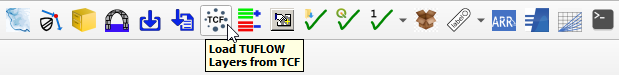
- Go to the location of the TUFLOW model and navigate to the TUFLOW\runs folder. Select the TCF.
- In the Load Layers window, select:
- Ordering Options: Alphabetical
- Grouping Options: Group by control file
- Raster Load Options: Load Normally
- Click ‘Open’ and ‘OK’.

Style the layers however you desire. Common steps to do this are:
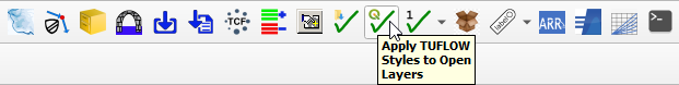
- Click on the ‘Apply TUFLOW Styles to Open Layers’ symbol from the TUFLOW Plugin toolbar.
- Create a hillshade of the DEM:
- In the QGIS Layers panel, right click on the Grid file and select 'Rename Layer'. Rename the layer to include 'Hillshade' in the filename. For example, 1D2D_Urban_Grid_copy > 1D2D_Urban_Grid_Hillshade.
- Right click on the Hillshade and select 'Properties'.
- In the Symbology tab, under 'Band Rendering' select the following options:
- Render type: Hillshade
- Z Factor: 3
- In the Transparency tab, set the 'Global Opacity' to 75%.
- Click 'Apply' and 'OK'.

Save the QGIS Workspace:
- From the top dropdown menu options, go to Project > Save As.
- Navigate to the file location containing the TUFLOW folder and save the workspace with the extension, .qgz.
One Dimensional (1D) SWMM Model Elements
Export 1D EPA SWMM Pipe Network Data from XPSWMM
Convert 1D XPSWMM hydraulics features into a EPA SWMM 5 INP file format for TUFLOW:
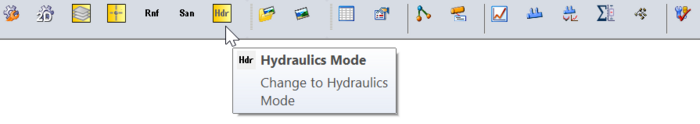
- In XPSWMM, select 'Hydraulics Mode' from the toolbar.
- From the XPSWMM top dropmenu, select File > Import/Export Data > Export to EPASWMM5. The exported INP file will be saved under the same name and in the same folder location as the .xp project file.
- When prompted to save changes, select 'Yes'.
- In Windows File Explorer, navigate to the folder containing the .xp project file and rename the exported INP file by adding 'HDR' to the file name. For example, 1D2D_Urban_001.inp > 1D2D_Urban_HDR_001.inp.
- Copy the renamed INP file into the TUFLOW\model\swmm folder. From this folder, drag and drop the .inp file into QGIS. This will open the 'GeoPackage - Create from SWMM inp ' tool from the QGIS Processing Toolbox.
- SWMM Input File (inp): Pre-populated
- CRS for GeoPackage: Select and appropriate Coordinate Reference System (CRS) for the model.
- GeoPackage output filename: Prepopulated to save the output GeoPackage file under the same name and in the same folder location as the SWMM input file.
- Click 'Run'. Once the tool is finished, click 'Close'.
- A dialog will appear. Select 'Add Layers' to open all vectors within the newly created SWMM GeoPackage file. By default, all items in the available list should have been selected.
- In the QGIS Layers panel, move the SWMM GeoPackage file to the top of the list. This will ensure the data within this database file is displayed above all other layers in the project.
- Inspect the attributes associated with the various objects in the GeoPackage to familiarize yourself with the data.

The process above has created a Nodes--Junctions layer, containing all the model nodes. In the Convert XPSWMM Model to Recommended TUFLOW Structure section, an improperly formatted layer of the same nodes was generated from XPSWMM. To prevent future errors, this layer should be removed from the QGIS workspace and deleted from its GeoPackage.
- In the QGIS Layers panel, open the tbc group (i.e. 1D2D_Urban_001.tbc). Right click the 2d_bc points layer and select 'Remove Layer...'.
- From the top dropdown menu options, select View > Panels. Tick on 'Browser Panel'.
- In the QGIS Browser panel, navigate to the TUFLOW\model\gis folder and open the GeoPackage layer tree.
- Note: Within the QGIS Browser panel, there is a dropdown directory, 'Project Home'. This directory is a shortcut to the location where the QGIS workspace is saved.
- Right click 2d_bc points layer (i.e.1D2D_Urban_001_2d_bc_P) and select Manage > Delete Layer.
Correct SWMM Nodes--Junction/Outfall Model Design
XPSWMM used a modified version of the EPA SWMM engine. Unlike traditional EPA SWMM networks that require Nodes--Junctions at the upstream end of culverts and Nodes--Outfalls at the outlets, XPSWMM uses Nodes--Junctions in all locations. TUFLOW's implementation of SWMM has retained the traditional EPA SWMM structure. Due to this fundamental difference in approach, some manipulation of the XPSWMM Nodes--Junctions information is necessary.
- In the QGIS Layers panel, select (left click) Nodes--Junctions to make it the active dataset.
- Go to Processing > Toolbox from the top dropdown menu options to open the Processing Toolbox.
- Go to TUFLOW >> SWMM in the processing tool list and select 'Junctions - Downstream junctions to outfalls'. This opens the dialog shown below.
- Input Junctions: Nodes--Junctions (this is prepopulated as Nodes--Junctions is the active dataset).
- Input Conduits: Click '...' and tick on Links--Conduits
- Modified Junctions Layer: Leave this field blank so the tool writes the data to a temporary file. It will not be used.
- Modified Outfalls Layer:
- Click '...', select 'Save to GeoPackage...'.
- Navigate to the TUFLOW\model\swmm folder and select the HDR GeoPackage file created in the Convert XPSWMM Model to Recommended TUFLOW Structure section. Click 'Save'.
- A dialog will open. In the 'Layer Name' field, write Nodes--Outfalls. It is important that this layer is named correctly so it is recognized by the other TUFLOW SWMM processing tools.
- Click 'OK'.
- Click 'Run'. Once the tool is finished, click 'Close'.
- The temporary junctions layer, Modified junctions layer, and the new outfalls layer, Nodes--Outfalls, will appear in the QGIS Layers panel.
- In the QGIS Layers panel, right click Modified junctions layer, and select 'Remove Layer..'.
- In the QGIS Layers panel, select (left click) Nodes--Outfalls and toggle off editing.
To complete the update process, it is necessary to remove the junction nodes from Nodes--Junctions that coincide with the nodes created in Nodes-Outfalls. While this can be done manually, the steps below illustrate an automated process using a processing tool.
- In the QGIS Layers panel, select (left click) Nodes--Junctions and toggle on editing.
- Use the 'Select Features' tool to select all nodes included in the Nodes--Junctions layer. This will change their color to bright yellow.
- In the Processing Toolbox, go to 'Vector Selection' and select 'Select within distance'. This opens the dialog shown below.
- Select features from: Nodes--Junctions (this is prepopulated as Nodes--Junctions is the active dataset).
- By comparing to the features from: Click the drop down menu and select Nodes--Outfalls.
- Where the features are within: '0.1 meters'
- Modify current selection by: 'selecting within current selection'
- Click 'Run'. Once the tool is finished, click 'Close'.
- In the QGIS Layers panel, right click Nodes--Junctions and select 'Open Attribute Table'.
- In the attributes table, only some of the junction nodes will be selected. Select 'Delete selected features' to delete these nodes. Close the attribute table.
- Toggle the editing off to save the edits.
1D/2D Pipe Network Pit (Inlet Usage) Connections
Inlet usage connections establish the 1D/2D linkages between the ground surface, defined in 2D, and the 1D SWMM pipe network. Physically, these features come in various forms and dimensions; however they are commonly referred to as kerb inlets, with or without associated grates. An example is shown in the image below.

Transfer of inlet usage connection information from XPSWMM to TUFLOW involves a three step process:
- Export data from XPSWMM.
- Convert the exported data into a TUFLOW SWMM compatible format.
- Make minor edits to correct for snapping deficiencies in the XPSWMM export tools.
Export Data from XPSWMM
- In XPSWMM, select 'Hydraulics Mode' from the toolbar.
- In the XPSWMM Layers panel, right click Nodes and select 'Export To GIS File...'. This will open a dialog.
- Select the GIS File: Click the '...' and navigate to the TUFLOW\model\swmm folder. Enter an appropriate filename and set the file type to ESRI (*.shp). For example, 1D2D_Urban_Node_Export_001.shp
- Click 'Node Data and Results' to expand the folder tree. Go to Node Data and Results > Hydraulics Node > HDR Node Data. Double click to select the following items:
- Node 2D Inflow Capture Flag
- Ground Elevation (Spill Crest)
- 2D Inflow Capture Coefficient
- 2D Inflow Capture Exponent
- In the right-hand table, the items above, along with 'Node Name', 'Node X' and 'Node Y', should be selected.
- In the 'Custom Name' column, select each entry and shorten the text to less than 10 characters. For example, 'Node 2D Inflow Capture Flag' > 'NodeIn' and 'Ground Elevation (Spill Crest)' > 'Ground'.
- Click 'Export'. A message will appear reporting how many nodes were exported.
Convert Exported Data into TUFLOW SWMM Format
- In Windows File Explorer, navigate to the TUFLOW\model\swmm folder. Drag and drop the node export .shp file into QGIS.
- In the QGIS Layers panel, select (left click) the node export layer.
- In the Processing Toolbox, go to TUFLOW >> SWMM and select 'Convert - XPSWMM GIS inlet layers to SWMM'. This opens the dialog shown below.
- GIS layer with inlet information: This is prepopulated as the node export layer is the active dataset.
- Inlet name field: 'Node Name'
- Inlet elevation field: 'Ground'
- Inlet 2d capture flag field: 'NodeIn'
- Inlet discharge equation coefficient field: 'Coeff'
- Inlet discharge exponent field: 'Exponent'
- Inlet connection width: This defines the number of 2D cells associated with the 1D/2D connections. Typically, this should match the 2D cell size of the model.
- CRS: Select the models' Coordinate Reference System (CRS).
- SWMM inp file (for inlet definition and curves):
- Click '...', and select 'Save to File...'.
- Navigate to the TUFLOW\model\swmm folder. Choose an appropriate .inp file name. For example, swmm_inlet_curves_XP_001.inp. This tool will also create a .gpkg file with the same data and name; saved in the same file location, i.e. swmm_inlet_curves_XP_001.gpkg.
- Click 'Save'.
- GeoPackage file for inlet usage:
- Click '...', and select 'Save to File...'.
- Navigate to the TUFLOW\model\swmm folder. Choose an appropriate .gpkg file name. For example, swmm_iu_XP_001.gpkg.
- Click 'Save'.
- Click 'Run'. Once the tool is finished, click 'Close'.
- Remove the node export layer from the QGIS workspace.
- In Windows File Explorer, navigate to the TUFLOW\model\swmm folder. Drag and drop the two new GeoPackage databases (i.e. swmm_iu_XP_001.gpkg and swmm_inlet_curves_XP_001.gpkg) into QGIS (hold Ctrl to select multiple). Inspect the attributes associated with the objects in both GeoPackages.
Edit TUFLOW SWMM Data
Unfortunately, the snapping tolerance set by XPSWMM for its Node GIS Data Export function is larger than the underlying model information it is associated with. This can cause a slight offset in the data. To rectify this issue, we will use a processing tool designed to assist in this task.
- In the QGIS Layers panel, select (left click) the inlet usage layer (i.e. swmm_iu_XP_001) and toggle on editing.
- In the Processing Toolbox, select the 'Edit Features In-Place' tool
 . This allows the editing of an existing layer, instead of the creation of a new layer.
- Go to 'Vector geometry' in the processing tool list and select 'Snap geometries to layer'. This opens the dialog shown below.
- Reference Layer: Nodes--Junctions. This is the layer we want the inlet usage layer to snap to.
- Tolerance: '0.1 meters'
- Behavior: 'Prefer aligning nodes, insert extra vertices where required'
- Click 'Modify All Features'. Once the tool is finished, click 'Close'.
- Toggle off the editing for the inlet usage layer (i.e.swmm_iu_XP_001) to save the edits.
Edit 1D/2D Culvert Connections
In addition to the pipe network inlet usage 1D/2D connections, we also need to connect the 1D culvert inlet/outlets to the 2D. These features are typically associated with culverts located under raised roads or rail embankments, outlets from pipe networks into creeks, streams, or rivers, or open pipe network inlets and outlets linked to major stormwater drainage infrastructure, which often involves the modification of historically above-ground streamflows to an underground stormwater network. An example is shown in the image below.

In order to connect a 1D SWMM culvert to TUFLOW 2D, TUFLOW SWMM necessitates 1D/2D HX connection lines at the upstream (inlet) end of the culvert and 1D/2D SX connection lines at the downstream (outlet) end. This model schematization differs from that of the TUFLOW ESTRY and XPSWMM, which require 1D/2D SX connections both upstream and downstream, but aligns with the traditional requirements of EPA SWMM.

In the Convert XPSWMM Model to Recommended TUFLOW Structure section, the XPSWMM 1D/2D connections were converted into TUFLOW format. However, since we have included and edited the SWMM data (HDR, inlet curves, and inlet usage GeoPackages), this connections layer needs to be updated. We need to change the upstream SX connections to HX connections, create new upstream CN lines, and ensure that the connections are snapped to the pipe network.
- In the QGIS Layers panel, within the TBC group, select (left click) the 2d_bc lines layer (i.e. 1D2D_Urban_001_2d_bc_L) and toggle on editing. This layer contains the converted XPSWMM 1D/2D connections.
- In the Processing Toolbox, select the 'Edit Features In-Place' tool . This allows the editing of an existing layer, instead of the creation of a new layer.
- Go to 'Vector geometry' in the processing tool list and select 'Snap geometries to layer'. This opens the dialog shown below.
- Reference Layer: Links--Conduits. This is the layer we want the 2d_bc connections layer to snap to.
- Tolerance: '0.1 meters'
- Behavior: 'Snap end points to end points only'
- Click 'Modify All Features'. Once the tool is finished, click 'Close'.
- This tool has ensured that the 2d_bc connections layer is snapped to the pipe network.
- In the top dropdown menu options, select View > Toolbars. Tick on 'Snapping Toolbar'.
- Select the 'Enable Snapping'
 and 'All Layers > Advanced Configuration', an eye icon appears.
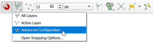
- Select the 'Edit Advanced Configuration'
 and tick on the 2d_bc connections layer and the Links--Conduits layer.
- From the 'Digitizing Toolbar', use the 'Add Line Feature' tool to create a CN line to each upstream connection.
- Use the 'Identify Features'
 tool to select an upstream 'SX' connection. A dialog will open.
- Change the 'Type' field to 'HX'.
- Repeat this for each upstream 'SX' connection.
- Toggle off editing for the 2d_bc connections layer to save the edits.

SWMM Hydrology
If the XPSWMM model includes EPA SWMM hydrology, the hydrology components can be brought across into TUFLOW SWMM.
First, to confirm the SWMM Hydrology runoff method has been used in the XPSWMM model, review the model settings. In XPSWMM, from the top dropdown menu options, go to Configuration > Mode Properties. Under 'Solve Mode', select 'Methods' Confirm 'SWMM Methods (64 bit)' is selected.

Convert 1D XPSWMM hydraulics features into a EPA SWMM 5 INP file format for TUFLOW:
- In XPSWMM, select 'Runoff Mode' from the toolbar.
- From the XPSWMM top dropdown menu options, select File > Import/Export Data > Export to EPASWMM 5. The exported INP file will be saved under the same name and in the same folder location as the .xp project file.
- When prompted to save changes, select 'Yes'.
- In QGIS, go to TUFLOW >> SWMM in the processing tool list and select 'GeoPackage - Create from SWMM inp '. This open the dialog shown below.
- SWMM Input File (inp): Navigate to the folder location of the .xp project file and select the recently exported INP file.
- CRS for GeoPackage: Select an appropriate Coordinate Reference System (CRS) for the model.
- GeoPackage output filename: Navigate to the TUFLOW\model\swmm folder. Save the file with the same name as the SWMM input file, but append 'RNF' to the filename. For example 1D2D_Urban_001.inp > 1D2D_Urban_RNF_001.gpkg.
- Click 'Run'. Once the tool is finished, click 'Close'.
- This tool has generated a Nodes--Junctions layer which is a duplicate of the Nodes--Junctions layer in the HDR GeoPackage. Thus, we will remove the RNF Nodes--Junctions layer.
- In QGIS, from the top dropdown menu options, select View > Panels. Tick on 'Browser Panel'.
- In the QGIS Browser Panel, navigate to the TUFLOW\model\swmm folder and open the RNF GeoPackage layer tree.
- Note: Within the QGIS Browser Panel, there is a dropdown directory, 'Project Home'. This directory is a shortcut to the location where the QGIS workspace is saved.
- Right click Nodes--Junctions and select Manage > Delete Layer.
- In Windows File Explorer, navigate to the TUFLOW\model\swmm folder. Drag and drop the RNF GeoPackage into QGIS.
- In the QGIS Layers panel, move the RNF GeoPackage below the other GeoPackages in the list. This will ensure the data within this database file does not cover the other layers in the project.
Note: For hydrology, TUFLOW has more advanced, workflow efficient 'Event Scenario Management' options than XPSMM. If your project requires the simulation of multiple hydrology events, please complete TUFLOW SWMM Module 4 and use the model design concepts in it to upgrade the configuration of your TUFLOW model to accommodate for the simulation of multiple events from a single model.

Update SWMM Nodes--Junction Attributes
The following GIS feature update to the Nodes--Junctions attributes will finalize the SWMM portion of the TUFLOW model. This is typically the final step in the model building process, as the recommended attributes for junction node vary depending on whether the node is associated with inlet usage connections, 1D/2D culvert connections and SWMM hydrology sub-catchments.
- In the QGIS Layers panel, select (left click) Nodes--Junctions and toggle on editing.
- In the Processing Toolbox, select the 'Edit Features In-Place' tool. This allows the editing of an existing layer, instead of the creation of a new layer.
- Go to TUFLOW >> SWMM in the processing tool list and select the 'Junctions - Set attributes ' processing tool. This opens the dialog shown below.
- Input Subcatchment layers: If available, select Hydrology--Subcatchments.
- Input Inlet Usage Layers: If available, select the inlet usage layer (i.e. swmm_iu_XP_001)
- Input BC Connection Layers: If available, select the 2d_bc connection layer (i.e. 1D2D_Urban_001_2d_bc_L).
- General Options:
- Maximum Depth Option (Ymax): 'Set to 0.0'.
- Nodes receiving subcatchment flows option (if connected to 2D): 'Set Apond = 0.0; Ksur = 0.0 (overwrites options below)'.
- Nodes connected to 2D without Inlets:
- Ysur: 0
- Area of ponding: This value should match the 2D cell area associated with 1D/2D culvert connections.
- Nodes connected to 2D with Inlets:
- Maximum depth (Ymax) option: 'Use global option'
- Ysur: 0
- Area of ponding: This value should match the 2D cell area associated with the Inlet Usage connections.
- Nodes without 2D Connection:
- Surcharge Depth: This value should be a value higher than any expected water level in the model.
- Area of ponding: 1
- Select 'Modify All Features'. Once the tool has finished, click 'Close'.
- Turn off editing to save the edits.
- View the attributes within Nodes--Junctions to verify the data processing has been completed correctly.
For a summary of the attributes associated with the Nodes--Junctions layer, refer to TUFLOW 2023-03-AD Release Notes (Table A.30) and the SWMM Reference Manual - Volume 2 (Hydraulics).
Export INP Files
SWMM cannot directly read GeoPackage databases. Therefore, we need to convert all three GeoPackage files (HDR, RNF and inlet curves) into the SWMM INP file format. Both the HDR and RNF GeoPackages contain a Project--Options section, which are identical as they were extracted from the same XPSWMM model. These options are necessary for executing the SWMM simulation. Since Project--Options is already included in the HDR and RNF, it is not needed in the inlet curves INP file.
Note: The inlet usage GeoPackage does not need to be converted to a SWMM inp file. Since it contains only one layer, it can be directly read into TUFLOW SWMM.
- In QGIS, go to TUFLOW >> SWMM in the processing tool list and select 'GeoPackage - Write to SWMM inp'.
- In the tool window, click the '...' and navigate to the TUFLOW\model\swmm folder. Select the HDR GeoPackage file.
- Click 'Run'.
- Once the tool has finished, click the 'Parameters' tab.
- Repeat steps 2 and 3 for the RNF and inlet curves GeoPackages.
- Once the tool has finished, click 'Close'.
- The three SWMM INP files will be located in the TUFLOW\model\swmm folder, with each file sharing the same filename as their respective GeoPackages. For example, 1D2D_Urban_HDR_001.gpkg > 1D2D_Urban_HDR_001.inp.
Link 1D SWMM and 2D TUFLOW Model
The linking between the 1D SWMM and the 2D TUFLOW model is established within the TUFLOW control files, which are essential for running TUFLOW-SWMM simulations. The following steps outline the basic commands needed to complete the linking process and execute the model. These commands may need to be modified depending on the modeling task.
Model Projection
Simulation Control Files
The following steps will require use of a text editor. The tutorial demonstration uses Notepad++. For its configuration information refer to Notepad++ Tips. For a clean and organized model, it is recommended to name all the TUFLOW control files similarly. For example, 1D2D_Urban_001.tscf, 1D2D_Urban_001.tbc, 1D2D_Urban_001.tgc and 1D2D_Urban_5m_001.tcf.
Note: For this demonstration, all commands will reference the datasets in the provided conversion model. Please update these references with the filenames sued in your model.
Clean TUFLOW Control Files
In the process of converting a model, the Convert TUFLOW Model GIS Format processing tool adds commands to the TUFLOW control files created by XPSWMM. While these control files contain most of the essential commands, they typically lack sufficient information to enable the mode to run smoothly. Additionally, these files often contain unecessary and/or outdated commands. It is recommended to 'clean up' the control files before running the simulation.
- In Windows File Explorer, navigate to the TUFLOW\runs folder and open the TCF into a text editor (Notepad++ is recommended).
- Below is a list of commands in the TCF that can be removed or commented out.
Check MI Save Date == Mass Balance Output Interval (s) == MI Projection == CSV Time == MI Projection Check == Viscosity Formulation == Timestep (s) == Viscosity Coefficient == Cell Wet/Dry Depth == SX ZC Check == Read GIS XP Nodes == SX Storage Approach == Simulations Log Folder == HX ZC Check == Store Maximums and Minimums == Mass Balance Corrector == Mass Balance Output == - The table below displays the TCF commands to be updated:
Original Command Updated Command GPKG Projection == 1D2D_Urban_001_proj GPKG Projection == ?? Write Check Files == OFF Write Check Files == ..\check\ Output Folder == ..\results\Output Output Folder == ..\results\ Log Folder == log\Log Output Folder == log Map Output Data Types == qVdhZ0 Map Output Data Types == q V d h Z0 Map Output Format == XMDF Map Output Format == XMDF TIF
TUFLOW Control File (TCF)
The TCF file references all the control files, specifies time and output controls.
- In Windows File Explorer, navigate to the TUFLOW\runs folder and open the TCF into a Text Editor (Notepad++ is recommended).
- Add the following command to the 'Model Inputs' section:
SWMM Control File == ..\model\1D2D_Urban_001.tscf ! Reference the SWMM (1D) Control File
Video?
TUFLOW SWMM Control File (TSCF)
The TUFLOW SWMM Control File (TSCF) is used to control the SWMM input data flow. All 1D SWMM files and commands are referenced in the TUFLOW SWMM Control File.
- In Windows File Explorer, navigate to the TUFLOW\model folder and create a new blank text file with the extension .tscf.
- Open the TSCF into a Text Editor (Notepad++ is recommended) and add the following commands.
Read SWMM == ..\swmm\1D2D_Urban_HDR_001.inp ! 1D SWMM Pipe Network input file
Read SWMM == ..\swmm\1D2D_Urban_RNF_001.inp ! 1D SWMM Hydrology input file
Read SWMM == ..\swmm\swmm_inlet_curves_XP_001.inp ! 1D SWMM Inlet Curves input file
Read GIS SWMM Inlet Usage == ..\swmm\swmm_iu_XP_001.gpkg >> inlet_usage ! 1D SWMM Pipe Network Inlet Usage layer
<<Video>>
TUFLOW Boundary Control File (TBC)
The TUFLOW Boundary Control File (TBC) contains information regarding the location of boundary conditions and internal links within the model.
- In Windows File Explorer, navigate to the TUFLOW\model folder and open the TBC into a text editor (Notepad++ is recommended).
- Remove the reference to the 2d_bc points layer. This layer was removed from the model GeoPackage in the Export 1D EPA SWMM Pipe Network Data from XPSWMM section.
- The TBC should reference the 2D boundary condition layer and the 1D/2D connection layer. In this case, they are both included in the 2d_bc connections layer.
Read GIS BC == 1D2D_Urban_001_2d_bc_L ! Reads in 2D boundaries and links 1D SWMM culverts to the 2D TUFLOW domain
Video
TUFLOW Geometry Control File (TGC)
The TUFLOW Geometry Control File (TGC) contains a series of commands that build the geometry model. At its minimum, the TGC contains:
- Information on the size and orientation of the grid;
- Grid cell codes (whether cells are active or inactive);
- Bed / ground elevations; and
- Bed material type or flow resistance value.
The TGC requires no updates; however, it is recommended to review the TGC before running the simulation to ensure all commands are correct.
TUFLOW Control File (TCF)
The TCF file references all the control files, specifies time and output controls.
In the Convert XPSWMM Model to Recommended TUFLOW Structure section, the Convert TUFLOW Model GIS Format processing tool utilizes the TUFLOW control files generated by XPSWMM to construct the TUFLOW SWMM model control files. During this process, the tool updates the commands within the TUFLOW control files to align with the requirements of a TUFLOW SWMM model. However, since the original control files were intended for use with XPSWMM, they lack the commands required to execute a TUFLOW simulation. Additionally, these files often contain unnecessary and/or outdated commands.
In the section above, the TBC was edited to reflect the model updates implemented during the conversion process, while no updates were necessary for the TGC. However, the TCF requires updating to ensure the TUFLOW SWMM model runs smoothly.
- Remove or comment out the commands listed below.
Check MI Save Date == Mass Balance Output Interval (s) == MI Projection == CSV Time == MI Projection Check == Viscosity Formulation == Timestep (s) == Viscosity Coefficient == Cell Wet/Dry Depth == SX ZC Check == Read GIS XP Nodes == SX Storage Approach == Simulations Log Folder == HX ZC Check == Store Maximums and Minimums == Mass Balance Corrector == Mass Balance Output == - Make the following updates:
Original Command Updated Command GPKG Projection == 1D2D_Urban_001_proj GPKG Projection == ?? Write Check Files == OFF Write Check Files == ..\check\ Output Folder == ..\results\Output Output Folder == ..\results\ Log Folder == log\Log Output Folder == log Map Output Data Types == qVdhZ0 Map Output Data Types == q V d h Z0 Map Output Format == XMDF Map Output Format == XMDF TIF - Add the following commands:
Tutorial Model == ON ! Required command to run this tutorial model licence free
GIS Format == GPKG ! Specify GPKG as the output format for all GIS files
Solution Scheme == HPC ! Heavily Parallelised Compute, uses adaptive timestepping
Hardware == CPU ! Replace with "Hardware == GPU" if GPU available
Start Time == 0 ! Specifies the simulation start time (0 hours)
End Time == 3 ! Specifies the simulation end time (3 hours)
- Add the following command to reference the TUFLOW SWMM Control File (TSCF):
SWMM Control File == ..\model\1D2D_Urban_001.tscf
Optional: Format TUFLOW Control Files
In the sections above, we removed unnecessary commands from the TUFLOW control files and introduced additional commands to ensure the TUFLOW SWMM model runs smoothly. In this section, we will format and organize the TUFLOW control files to enhance readability, thereby improving the overall functionality of the model. This can be done by:
- Using relative file paths to specify the location of various files and layers in the model.
- Including a title at the beginning of each control file. For example, ! TUFLOW CONTROL FILE (.TCF) defines the model simulation parameters and directs input from other data sources.
- Adding headings to sections of the control file. For example, ! MODEL INITIALIZATION could be used as a header for the commands required to initialize the TUFLOW SWMM model.
- Utilizing comments to explain the purpose of commands. For example, Spatial Database == ..\model\gis\1D2D_Urban_001.gpkg ! Specify the location of the GeoPackage Spatial Database.
If using the provided model conversion dataset, the final Control files should look like this:
insert images when dataset finalised
Converted Dataset
After completing the model conversion steps outlined above, you can download the converted TUFLOW SWMM model dataset using the following link: <<link>>
This dataset includes both the original XPSWMM model and the converted TUFLOW model. We recommend checking your converted TUFLOW model against the provided one to ensure all conversion steps were completed correctly.
Feedback / Suggestions
If you have any suggestions to be included in these pages, please email support@tuflow.com.
| Up |
|---|