1D Syphons: Difference between revisions
No edit summary |
No edit summary |
||
| Line 13: | Line 13: | ||
The most appropriate approach to model a syphon is to use a M channel described in Section 5.8 in the Manual. An M channel can be used to define a matrix of flows between two invert levels based on their respective depths. If this matrix of flows through the syphon can be calculated, or if they are given as part of the operational instructions, then they can be input in .csv form as below, where negative values indicate flows going from downstream to upstream. |
The most appropriate approach to model a syphon is to use a M channel described in Section 5.8 in the Manual. An M channel can be used to define a matrix of flows between two invert levels based on their respective depths. If this matrix of flows through the syphon can be calculated, or if they are given as part of the operational instructions, then they can be input in .csv form as below, where negative values indicate flows going from downstream to upstream. |
||
[[File:Syphon matrix w10.jpg| 600px]] |
|||
=== Storage Nodes & Additional Losses === |
=== Storage Nodes & Additional Losses === |
||
Alternatively, 1d_nwk nodes can be used to account for the storage of the vertical portion of the syphon as the images shown below. This configuration essentially estimates the flows conveyed though the syphon based on the upstream and downstream water level and the hydraulic property of the bottom pipe. |
Alternatively, 1d_nwk nodes can be used to account for the storage of the vertical portion of the syphon as the images shown below. This configuration essentially estimates the flows conveyed though the syphon based on the upstream and downstream water level and the hydraulic property of the bottom pipe. It is strongly recommended to calibrate the model result against measurement data to check the accuracy or if measurement data are not available, conduct sensitivity testing. |
||
[[File:Syphon storagenodes.jpg]] |
|||
==== Syphon Losses ==== |
==== Syphon Losses ==== |
||
The main losses for syphon are: |
The main losses for a syphon are: |
||
*entry exit losses |
* entry and exit losses |
||
*friction at pipe wall |
* friction at pipe and wall |
||
*bend |
* bend losses |
||
Bend losses (or any extra loss) through the syphon can be accounted for using the Form_Loss attribute of the pipe. |
|||
The following figure provides loss values for common bend types: |
|||
[[File:Bend losses.jpg]] |
|||
Revision as of 14:02, 16 July 2024
Introduction
A syphon (or siphon) is a hydraulic structure used to transfer water from one location to another, typically over an elevation difference, without the need for pumping. A syphon operates based on the principle of atmospheric pressure and gravity.
The components of a syphon are:
- Inlet: Located at the higher water level, where water enters the siphon.
- Outlet: Positioned at the lower water level, where water exits.
- Riser: The vertical section that rises from the inlet to the crest of the U-shape.
- Downleg: The section that descends from the crest to the outlet.
1D Configuration
There are two approaches to model a syphon system in TUFLOW.
Matrix Flows
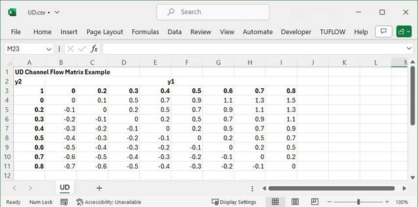
The most appropriate approach to model a syphon is to use a M channel described in Section 5.8 in the Manual. An M channel can be used to define a matrix of flows between two invert levels based on their respective depths. If this matrix of flows through the syphon can be calculated, or if they are given as part of the operational instructions, then they can be input in .csv form as below, where negative values indicate flows going from downstream to upstream.
Storage Nodes & Additional Losses
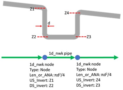
Alternatively, 1d_nwk nodes can be used to account for the storage of the vertical portion of the syphon as the images shown below. This configuration essentially estimates the flows conveyed though the syphon based on the upstream and downstream water level and the hydraulic property of the bottom pipe. It is strongly recommended to calibrate the model result against measurement data to check the accuracy or if measurement data are not available, conduct sensitivity testing.
Syphon Losses
The main losses for a syphon are:
- entry and exit losses
- friction at pipe and wall
- bend losses
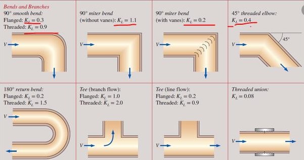
Bend losses (or any extra loss) through the syphon can be accounted for using the Form_Loss attribute of the pipe.
The following figure provides loss values for common bend types:


