FM Tute M01 QGIS 1D2D Links
- Import in an empty 2d_bc_empty_L.shp layer from within the FMT_tutorial\FMT_M01\TUFLOW\model\gis\empty folder.
- Save the empty layer as 2d_bc_FMT_M01_HX_001_L.shp in the FMT_tutorial\FMT_M01\TUFLOW\model\gis folder.
- Open the 1D_2D_HX_Links_L.shp GIS layer from Module_Data\Module_01\gis folder. Select all objects from within this layer, copy and paste into 2d_bc_FMT_M01_HX_001_L.shp.
- Interrogate one of the lines running along the banks of the watercourse. These lines are the 1D/2D boundary links and have been assigned a type ‘HX’.
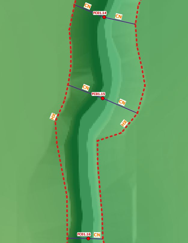
- Interrogate one of the lines connecting the x1D node to the HX line. These are the connection or ‘CN’ lines that read the water level from Flood Modeller and transfers this to the HX line. In the figure below, the water level is calculated in Flood Modeller at the nodes FC01.16, FC01.15 and FC01.14. These water levels are linearly interpolated along the lengths of the HX line on each of the left and right banks of the watercourse. When the water level exceeds the ZC elevation of the boundary cell, water is able to flow out onto the TUFLOW 2D floodplain.
- The CN and HX lines between nodes FC02.06 and FC02.01d along the tributary have not been digitised. Digitise these lines to connect the nodes to the 2D domain.
To digitise the CN lines, make the 2d_bc_FMT_M01_HX_001_L.shp layer editable and ensure snapping has been turned on. For each node in the 1d_x1d_FMT_M01_nodes_001_P.shp layer, draw a line from the node to the HX line. The line must snap to both the node and the HX line. Draw two lines for each node, one to the left bank and one to the right bank. In the 'Type' attribute of each line, type 'CN'.
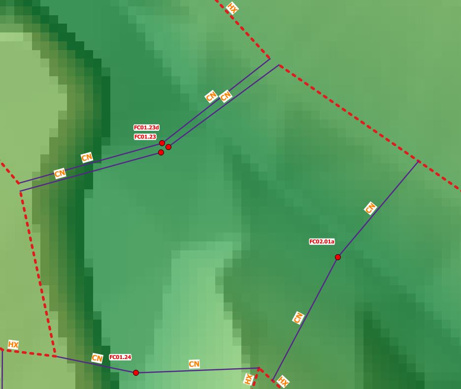
The figure below shows how the nodes are connected at the confluence. Note that all Flood Modeller nodes at the junction are present within the 1d_x1D_nodes layer, and are connected to the 2D domain. The HX lines are broken around the junction. - Once all the CN and HX lines have been digitised along the tributary, save the file.
Introduction
In this section we will apply a water level boundary to the 2D cells along the 1D/2D interface. In the 2D boundary condition (2d_bc) GIS layer, we define the location at which this link occurs. The 2D water level applied at the 2D boundary cells is calculated in the 1D Flood Modeller component. The terminology used in TUFLOW is a HX type boundary on the 2D cells, with the H indicating that a Head (water level) boundary is used and the X indicating the value is coming from an eXternal model (in this case Flood Modeller).
Depending on the water level in the surrounding 2D cells, flow can either enter or leave the HX cells. The volume of water entering or leaving the 2D boundary is added or subtracted from the 1D Flood Modeller model to preserve volume. We must connect the HX lines to the 1D Flood Modeller model. This is done using CN type lines in the 2d_bc layer, where a CN line is connected to the HX line, the water level from the 1D Flood Modeller nodes is transferred to the HX line. In between 1D nodes, a linear interpolation of water level is applied. This is shown in the figure below.

Once the water level in Flood Modeller exceeds the elevation in the boundary cell water can enter or leave the model. Similar to a Flood Modeller lateral spill or lateral inflow, the discharge is distributed laterally along the length of the HX line. Note that it is the elevation of the HX boundary cell centres that determines when the spill starts to occur and not the cross section within Flood Modeller. If there is a levee or flood defence, it is important that we use breaklines in the model to ensure that the elevations of the 2D cells are consistent with the levee crest. This will be described in the next section of the tutorial. The next four images show a section view of the 1D/2D link and how this may progress during a flood event.
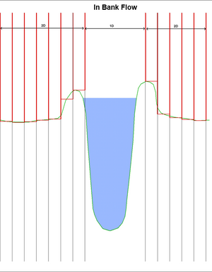
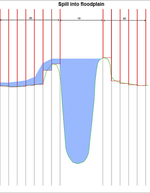
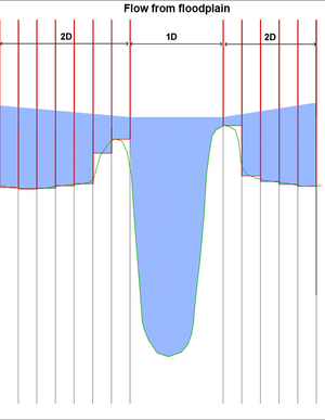
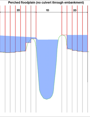
Often HX lines are located along the top of a levee (natural or artificial) or flood defence running along the river bank. When carving a 1D channel through a 2D domain, the HX line must be either on the top of the levee or on the inside of the levee (closest to the channel). If the HX line is located on the other side of the levee away from the channel, the effect of the levee on water flow is not modelled. In the sections above, it can be seen that the boundary cell is along the levee and the interaction between the channel and the floodplain (1D and 2D) occurs at the correct elevation.
Method
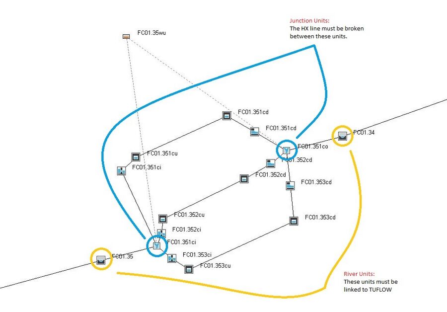
Note that where there are junctions within the Flood Modeller 1D model (i.e. at structures), both the nodes immediately upstream and downstream must be connected to TUFLOW. Refer to the below figure where the junctions are circled in blue and the upstream and downstream RIVER units are circled in yellow. The HX lines must be broken between the junctions as this is a requirement of a linked Flood Modeller – TUFLOW model.
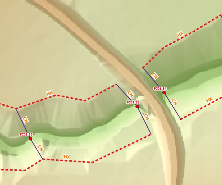
In the example below, the HX lines are broken between FC01.35 and FC01.34 as a culvert is located between these nodes.
Key Tip!
The digitised direction of the HX and CN lines is not important. The CN lines however should be digitised approximately perpendicular to the direction of flow. Two CN lines are digitised for each node and connected to the HX boundary lines along the left and right banks. The HX boundary lines should be digitised along the top of each bank such that the width between the lines approximately correlates to the width of the 1D channel.
Please return to the Flood Modeller Tutorial Model.