Tute M04 SMS Simulation Setup Archive
SMS writes out all necessary files such as .tcf, .ecf, .tgc, .tbc, bc_dbase etc when Export TUFLOW files command is executed. For proper linkage of the files, a Geometric component and Simulation should be set up correctly. Follow these steps to configure the run.
Geometric Components
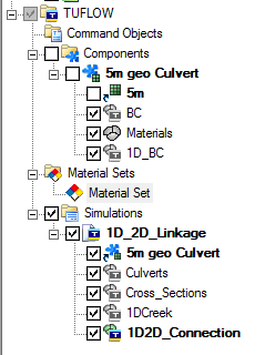
- In the project explorer, find a folder named TUFLOW | Components. Under this folder, there should be a geometric component named 5m geo Culvert already created from Module02.
- Make sure it has the following items. If anything is missing, drag it from the list under Map Data. If there is any extra item, remove it (Right click | Delete).
- 5m grid
- BC Coverage
- Materials Coverage
- 1D_BC Coverage
Material Sets
The Material set item in the project explorer is used to define Manning's roughness values for each land use type in the Materials coverage.
- Under the Material Sets folder, right click Material Set and select Properties. This will open the TUFLOW Material Properties dialog. Review Manning's n values for the various material types. Click OK when done.
Simulation set up
Several TUFLOW simulations can be created using various combinations of the same geometric components, coverages and material sets. Since we have set up necessary model geometry components and also defined the material properties, we will go ahead and create a simulation run.
- In the project explorer, right click Simulations folder and select New Simulation.
- Rename the simulation (named Sim by default) to 1D_2D Linkage.
- Drag 5m geo Culvert geometric component under this simulation.
- Similarly, drag the following coverages directly under the simulation:
- Culverts
- Cross_Sections
- 1DCreek
- 1D2D_Connections
- The project explorer should look something like this:

In the following steps we will define other model controls
2D Model Control
- On the project explorer, right click simulation 1D_2D_Linkage and select 2D Model Control which will open TUFLOW 2D Model Control dialog.
- On the left hand side of the dialog, there is a list of different categories of model control. Click on Time and define the following:
- Start time (hrs): 0
- End time (hrs): 3
- Timestep (s): 1.5
- Number of iterations: 2
- Click on Output Control and define the following:
- Start time: 0 hrs
- Interval: 300s
- Display interval: 6 timesteps
- Make sure Depth, Water Level and Velocity Vectors datasets are turned on.
- Click on Water Level and define the following:
- Initial Water Level (m): 36.5
- Click on BC and make sure 100 year has been selected under BC event name field.
- Click OK.
1D Model Control
- On the project explorer, right click simulation 1D_2D_Linkage and select 1D Control which will open the 1D Control dialog.
- On General tab, enter 0.75sec for Timestep (s) and 300 sec for Output Interval (s).
- Click OK.
Conclusion
Now we have set up the simulation and defined all the Model Control Parameters, let's proceed to Run the Simulation.