Tutorial Module13 Archive
- A polygon to lower the cells to allow flow through the breach
- A point which will be the trigger point
- Create the breach polygon and point layer. These can be digitised or copied from the Module Data. Ensure the polygon extends slightly upstream and downstream of the road, to ensure the breach opens a flowpath.
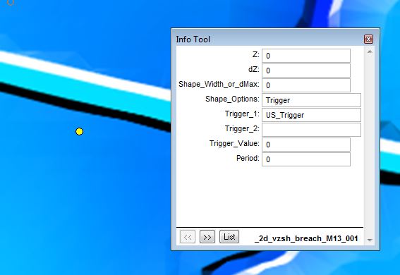
- Enter the attributes on the trigger point. The point attributes are shown below. Under "Shape_Options" the Trigger sets the point as a trigger location and not an elevation point (the Z attribute is not used). The fifth attribute "Trigger_1" is the name of the trigger, in this instance US_Trigger.
- Enter the attributes for the breach polygon. The polygon attributes are shown below. The first four attributes relate to the final elevation of the model. The "Z" attribute is set to 40.6, this will be the final elevation after the breach is finished. The "Shape_Options" is set to MIN NO MERGE, the "no merge" option prevents the elevations from being merged with the surrounding elevations. The values will be stamped onto the existing elevations. The "min" option prevents the breach from raising the elevations if these are already below 40.6.
The next four attributes set the breach attributes. In the "Trigger_1" attribute, the name of the trigger is set, the US_Trigger ties the polygon to breach based on the trigger point above. The "Trigger_Value" is the water level at the point. In this case when the water level reaches 42, the breach will begin.
The "Period" attribute sets how long the breach takes from the initial movement, to reaching the final elevations. In this case it has been set to 0.25 hours (15 minutes). - From the TUFLOW\runs\ folder, open the Module 4 control file (M04_5m_001.tcf) and save a copy of this as M13_5m_001.tcf.
- In the TUFLOW\model\ folder, save a copy of the module 4 geometry control file (M04_5m_001.tgc) and save this as M13_5m_001.tgc.
- In the newly created geometry control file, we need to read in the variable z shape. At the end of the file enter the following text:
MapInfo Users Read GIS Variable Z Shape == mi\2d_vzsh_breach_M13_001.MIF
Other GIS Read GIS Variable Z Shape == gis\2d_vzsh_breach_M13_001_R.shp | gis\2d_vzsh_breach_M13_001_P.shp
As the MapInfo files contain both the region and the point objects, this is read in from a single file. For the shapefile format, these are in separate files. The files make up a single dataset and therefore must be read on the same input line. The region and point files are separated with a vertical bar (|) also called a pipe character. If the breach contained points, lines and polygons all three files would need to be input. - Save the changes to the geometry control file.
- In the .tcf, you will need to update the reference to the newly created file. Change the command:
Geometry Control File == ..\model\mi\M04_5m_001.tgc
to:
Geometry Control File == ..\model\mi\M13_5m_001.tgc
- The model now contains the variable geometry breach. However, before we run the model, we will also get TUFLOW to output the bed level as a map output. Change the map output data types to:
Map Output Data Types == h V q d zh - We also want to ensure that the results files remain well organised. Change the command:
Output Folder == ..\results\M04\2d
to:
Output Folder == ..\results\M13\2d - Save the control file and run the model.
- Open the check files:
- MapInfo users import M13_5m_001_vzsh_zpt_check.mif
- For other GIS packages, open the M13_5m_001_vzsh_zpt_check_p.shp file.
- In this files there should be a series of TUFLOW elevation points (zpts) which contain more information about the variable geometry.
This shows the final elevation for the point, is also provides information on the trigger and period. The above shows the input as being read in as expected. - The model should now have finished running. Open the results in your preferred package (see earlier modules for a reminder).
- The results should show that the breach occurs shortly after 1 hour of simulation time. The elevation and velocity results are shown in the 1st image below. The depth and velocities are shown in the 2nd image. Both images are at 1:15min into the simulation.
Introduction
In this module a variable geometry layer will be setup. The layer used for this will be the 2D variable Z shape (2d_vzsh). These layers can be used to alter Zpts over the course of a simulation, to model, for example, breaching of embankments or even the filling of river due to a landslide. This layer is an advanced version of the 2D Z Shape (2d_zsh) used in previous modules (3 and 5). The variable Z shape has all the functionality of the Z shape layer and topography modifiers can be a mix of polygons, lines and points.
Refer to the TUFLOW Manual for further detailed information.
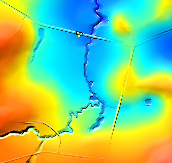
In this tutorial, the 2d_vzsh will be used to trigger a breach of the northern road embankment. The breach will be set to occur when the water level upstream of the just exceeds the road crest. Other options vzsh triggers can include a specific time or when the water level difference between two triggers exceeds a specified amount.
The 2d_vzsh layer is used to define the final topographic shape at the end of the breach and/or fill period.
GIS Layers
We are going to create two GIS objects:
In your preferred GIS package import a 2d_vzsh layer and save this. For MapInfo users the point and polygon can be in the same layer (2d_vzsh_breach_M13_001) and for QGIS or ArcMap these will need to be in separate files for the points (2d_vzsh_breach_M13_001_P.shp) and regions (2d_vzsh_breach_M13_001_R.shp).
The breach location is shown in the image below.


The GIS files are now ready to ready into the model control files. MapInfo users, don't forget to export the files into .MIF format.
Control Files
For this module we will start with the model created in module 4 as the starting point.
Check Files and Results
While the model is running, we will check that the variable geometry inputs are working correctly. This is a good place to look if the model is not behaving as expected, it is also useful for longer simulations to view the check files to ensure the inputs are correct.
Alternatives
If you would like to trigger the breach on the water level in the 1D (as opposed to the 2D), in the 2d_vzsh layer the trigger point must be snapped to the 1D node or channel end. For the "Shape_Options" attribute the entry must be Trigger 1D (not just “Trigger”), so TUFLOW knows to search for a snapped 1D node. Use the 2d_ vzsh_zpt_check layer to cross-check that the 1D node trigger has been correctly selected. In the working model provided, a second version of the model (M13_5m_002.tcf) has been provided. In this model a more advanced final geometry is utilised, this including points, lines and regions.
Conclusions
The variable z shape layer has used a water surface level trigger point to cause a simple breach in a road embankment.