Difference between revisions of "1D Bridges"
Rohan.king (talk | contribs) m (→Introduction) |
Rohan.king (talk | contribs) m (→Introduction) |
||
| Line 5: | Line 5: | ||
=Introduction= | =Introduction= | ||
The following section looks at bridges using the 1D component of TUFLOW, for information on bridges in the 2D domain please see the following section on [[TUFLOW_2D_Hydraulic_Structures | 2D hydraulic Structures]] and [[Tutorial_Module06#Bridge_Modelling_Option_3:_2D_Layered_Flow_Constriction | Module 6]]. <br><br> | The following section looks at bridges using the 1D component of TUFLOW, for information on bridges in the 2D domain please see the following section on [[TUFLOW_2D_Hydraulic_Structures | 2D hydraulic Structures]] and [[Tutorial_Module06#Bridge_Modelling_Option_3:_2D_Layered_Flow_Constriction | Module 6]]. <br><br> | ||
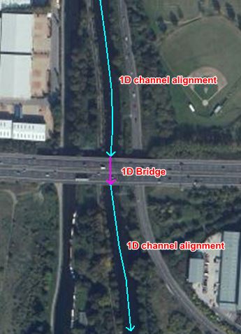
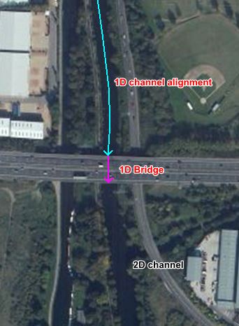
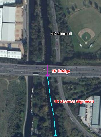
| − | As a typical rule-of-thumb, if the channel up stream &/or downstream of the bridge is modeled in 1D then the bridge should also be modeled in 1D | + | As a typical rule-of-thumb, if the channel up stream &/or downstream of the bridge is modeled in 1D then the bridge should also be modeled in 1D. Ideally any change in the channel from ESTRY 1D to 2D or vice-versa should also occur at a structure (i.e. bridge, culvert, etc) to facilitate the transition in solution schemes. The images below displays a typical preferred setup, however as is the case with hydraulic modeling your particular model situation may be different and therefore not always conform to these ideals.<br> |
<div><ul> | <div><ul> | ||
Revision as of 23:40, 1 February 2016
Page Under Construction
Introduction
The following section looks at bridges using the 1D component of TUFLOW, for information on bridges in the 2D domain please see the following section on 2D hydraulic Structures and Module 6.
As a typical rule-of-thumb, if the channel up stream &/or downstream of the bridge is modeled in 1D then the bridge should also be modeled in 1D. Ideally any change in the channel from ESTRY 1D to 2D or vice-versa should also occur at a structure (i.e. bridge, culvert, etc) to facilitate the transition in solution schemes. The images below displays a typical preferred setup, however as is the case with hydraulic modeling your particular model situation may be different and therefore not always conform to these ideals.
- Link to 2D section – this section explains 1D bridges only.
- Advice on when you would model a 1D bridge versus a 2D bridge (read module 6).
- Examples on a XZ and HW bridge type – pictures & csv examples
- Information on the checks you can carry out
- Theory
- Loss types (piers Kp, blockage Kb)
- Guidance/reference on how to derive losses
- Make sure to include section on automation of pier losses?
- Method A & Method B for bridges – refer to Bill’s post on 1.56 value
Irregular shaped bridges
Typical checks
Any further questions please email TUFLOW support: support@tuflow.com


