Ensight Tips
Introduction
Ensight is 3D Computational Fluid Dynamics (CFD) result viewing software developed by CEI Inc. The software can be downloaded from the CEI website.
This page contains a brief introduction to the software for the purpose of viewing and analyzing TUFLOW results. More advanced user tutorials are available via the CEI website. Ensight Tutorials.
If you have any suggestions to be included in these pages, please add them to the discussion page: Ensight Suggestions
Viewing Results
Data Preprocessing
Ensight requires an input file format which is different to the standard TUFLOW output types. RES_to_RES.exe is used to convert TUFLOW xmdf results into an Ensight compatible form. Directions how to do this are outlined here: RES_to_RES.exe
The utility will create the following three ensight file types:
- Ensight case file;
- Ensight geometry file;
- Ensight results files. A unique file is created for each result output variable and time step.
Ensight is a 3D computational fluid dynamics viewing software. An elevation dataset is required to lock the 2D TUFLOW results to a fixed horizontal plan (2D space). The TUFLOW model output result data type ZH is required for this purpose. This must first be specified as a TUFLOW command prior to running the simulation. Steps required to flatten the dataset are outlined in the flowing section, "Loading Data"
(eg. Map Output Data Types == h v q d ZH )
Loading Data
Run the TUFLOW utility RES_to_RES.exe to create the Ensight input data files from TUFLOW xmdf output.
Open the case file (*.case) in Ensight.

This will load the 'Part' titled: 2D TUFLOW Elements as Case Item 1.

Select the "Variables" tab within the data management window (bottom left) to view the model result scalar and vector datasets that were loaded.
Activate the relevant dataset that you would like to work with. In this example we have selected, Depth, Unit Flow, Velocity and Water Level.

These results can be viewed by creating an isosurface of the dataset within the 2D TUFLOW Elements Case Item.
Right Click 2D TUFLOW Elements Select >> Create >> Isosurfaces

Within the isosurfaces window:
- Select 'Advance' (top right)
- Enter a unique name for the dataset. This will become the child Part name. (2D TUFLOW Elements is the parent Part title)
- Select the Variable you would like to visualize (e.g. Depth)
- Set Creation Type = Isovolume
- Set Constraint = Banded
- Define the isovolume range. The upper and lower extreme values for the datasets are listed within the variables table (bottom left of the interface)


Update the variable display contouring:
- Select the newly created Part (right click)
- Select Color by >> Select Variable
- When contouring, select the relevant maximum dataset. For example, for time varying Depth data, select Max_Depth. This will lock the contouring to the range of the maximum dataset. Block colors and transparencies can also be defined using this selection.

The colour palette can be modified by selecting the defining dataset within the variable list:
Right Click >> Edit Palette

The final visualization step requires that the parent Part, 2D TUFLOW Elements be flattened. Ensight is a 3D computational fluid dynamics viewing software. Flattening the parent Part locks the TUFLOW dataset to a fixed horizontal plan (2D space).
- Select the parent Part, 2D TUFLOW Elements (right click)
- Select Edit
- Set the Coordinates scale factor = -1 *variable
- Set the Z variable = Fixed_Bathymetry. For this option to be available, the model result data type ZH must be defined as a TUFLOW output (eg. Map Output Data Types == h v q d ZH

Time series controls are located above the Parts window (top left).

Left Mouse Button
Holding the left mouse button whilst navigating in the viewport (graphics display)
- Navigating mouse up-down = rotate about horizontal screen X-axis
- Navigating mouse left-right = rotate about vertical screen Y-axis
- Ctrl-key plus up-down or left-right navigation = rotate about Z-axis extending outward from the screen
Right Mouse Button
Holding the right mouse button whilst navigating in the viewport (graphics display)
- Navigating mouse up-down or left-right = Model zooms in and out
- Ctrl-key plus right button acts as a pan operation
Middle Mouse Button (Scroll)
- Model zooms in and out
Shortcut Keys
F1 - Window will rotate about the screen X-axis by 45 degrees
F2 - Window will rotate about the screen Y-axis by 45 degrees
F3 - Window will rotate about the screen Z-axis by 45 degrees
Ctrl F1, F2, F3 rotates by -45 degrees about the screen axes
F4 - Spins the window – (try with the left mouse click)
F5 - Front view
F6 - Side view
F7 - Top view
F8 - Will return to last view before F5, F6 or F7 was pressed
F9 - Maximizes the graphics windows on the display; press F9 again or use Esc to go back
Data Calculations (Variable Calculator)
The calculator provides a powerful capability to derive new variables from existing variables and parts in the current data set.
Click the Variable Calculator icon to display the calculator.
To be continued...
Loading a Background Image
Background Images can be registered and added to a display.
The utility "Align Photo" is required to do this. This option is not available within the basic Ensight package. CEI Inc. should be contacted so that this utility can be added to your user define tools list.
Steps to load aerial imagery are:
- Select the Part which you would like to to apply the photo to.
- Double Click the “Align Photo” button from the user define tools list.
![]()
- A dialog will appear, asking you to select the Image File, and the corresponding World Coordinates File. Select the “Relative Position” option (EnSight models are currently stored in relative coordinates).
- Enter the Image File and World File.

- Select "OK".
- Select "Xref" and Yref" for the offsets.


Result Long-section Plot
Create a clip line in the location where you would like to extract results.
- Select the clip line icon
![]()
- Relocate the clip line. Selecting the centre is used to shift the location of the clip line. Selecting the start or end of the line can be used to alter the line extent.

- Select the parent Part 2D TUFLOW Elements
- Right Click >> Create >> Clip
- Name the Clip
- Select Tool = Line
- Select Extents = Finite

- Deselect the clip line tool.
![]()
- The clip should now remain within the view window and also show in the list of Parts

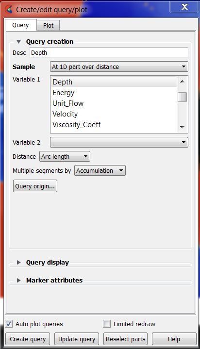
Variables are associated with the clip:
- Select the clip part (left clip in the Part window)
- Select query
- Select Sample = 1D part over distance
- Select the desired variable.
- For example Depth or Water_Level

Creating an Animation
Ensight can be used to present spatial and time series datasets dynamically within the same animation.

- Select File>>Export>>Animations
- Select Set format
- Select MPEG Movie
- Adjust the frame rate as appropriate
- Select Play and Reset
- Within Advanced Options, set the window type to Normal
- Select an appropriate output location and filename
