InfoWorks ICM to TUFLOW
Page In Progress
Introduction
This page outlines an approach for conversion of an InfoWorks ICM model to an Estry/TUFLOW format so that the 1D and 2D networks can be replicated in TUFLOW and used to generate a TUFLOW model.
InfoWorks ICM Network Conversion
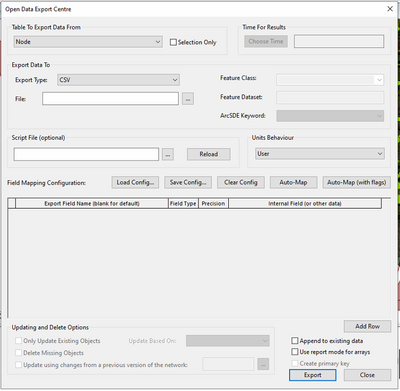
The InfoWorks data formats are native and therefore do require access to InfoWorks in order to convert the data. Note, that the following steps can be undertaken with a InfoWorks ICM Viewer licence and a full licence is not currently required. Although the InfoWorks ICM data formats are proprietry, it is relatively easy to use the Open Data Export Centre within InfoWorks ICM to export the model geometry data to open GIS layer formats (both shapefile and MIF/Mid format). The following steps will outline exporting to shapefiles but similar can be undertaken for MIF/MID. To open the Open Data Export Centre in InfoWorks ICM, open your network in the geoplan, select the relevant scenario, and go to Network->Export->Using Open Date Export Centre. You’ll be presented with the following dialog which allows you to export the InfoWorks network data to a variety of formats.
The data in InfoWorks ICM is stored in a number of database tables for each network type (eg, a separate table for nodes, conduits, 2D zones etc…).
Quick Export of Geometry Data
To get a full export of all the model files, with InfoWorks file formats, open the network and go to Network->Export->to Shape Files, slect the save location and the InfoWorks tables that you're interested in. Once exported the shape files can be opened in GIS to view the network table geometry and parameters.
Export to TUFLOW Formats
Within the Open Data Export Centre, it is possible to provide the Export Field Names and to map to them from the internal fields within the InfoWorks tables. This allows you to export directly to a shapefile with a TUFLOW format. For example, in the below image, the Export fields are set up to replicate the TUFLOW 1d_nwk file format. The relevant InfoWorks fields are then mapped to these to convert the InfoWorks format to a TUFLOW shapefile format.
Once the mappings have been set up, they can be saved as a Config file by using the ‘Save Config…’ option. Once a copy has been saved, the config file can be re-used to apply the same field mappings to subsequent exports. It should be noted that not all TUFLOW fields have an equivalent InfoWorks field and vice versa, therefore in some situations there will be some modeller input required to ensure the data is imported in the correct manner. Note in the 'Field type' column there are a number of different options specified. These are:-
- Constant-Allows the user to specify a constant value, for example, specify a constant value of '1' for the 'Code' field when exporting 2D Zones. It is also used when exporting a null value.
- Field-This is used to directly map an InfoWorks ICM field to a TUFLOW/Estry field. For example, copying the 'conduit_length' field to the 'Len_or_ANA' field for conduits.
- SQL-This allows a simple structured query language (SQL) script to export a combination of fields. For example, the ID is set to US_node_ID + link_suffix.
- Script-This allows the user to utilise a ruby script to filter out exported items or to convert fields. For example, for conduits, conduits with an InfoWorks shape type of 'CIRC' can be exported to TUFLOW link types 'C', shape types 'RECT' to 'R' and all others to 'I'.
It is also possible to export all InfoWorks fields at the end of the shape file and then use GIS to post-process this for conversions and other simple translations. An example configuration file which contains mappings for nodes, pipes, 2D components and 1D structures can be obtained from support@tuflow.com. The config file provides a good starting point for the conversion and further mapping of fields between InfoWorks and TUFLOW. Note, that currently the config file is set up to export geometry tables only and will not export tables containing cross-sections, head-discharge curves and similar. TUFLOW are not responsible for the accuracy of the config file and subsequent translation of data.
This approach can be used to export on a table by table approach although it is possible to save to the same config file. This allows one config file to set up all the mappings for each of the table exports. The downside of this approach is the time-consuming nature of exporting each table individually.
Use of Ruby Scripts
It’s possible to utilise the Ruby Scripting interface within InfoWorks ICM to speed up the export. A ruby script can be run to call the Open Data Export Centre, and export all requested tables, using a specified config file automatically, significantly reducing the number of button clicks. An example Ruby Script is available from support@tuflow.com which exports the tables as shown in Table 1.
Ruby Script Conversion
| Component | InfoWorks Table Name | TUFLOW File | Notes |
|---|---|---|---|
| 1D Nodes | Node | 1d_mh_pit | Headloss Approach is assumed to be TUFLOW’s default Engelund approach. Flow width is calculated as diameter based on the chamber area. |
| 1D Pipes | Conduit | 1d_nwk_pipe | Conduit shape ‘CIRC’ are set as Type ‘C’ and shape ‘RECT’ are set as type ‘R’, otherwise the conduit shape is set to I. Where ‘I’, the shape will need separately defining. Conduit Width/Height are converted from ‘mm’ to ‘m’. Manning's n roughness value are copied if roughness type is 'N'. |
| 1D Subcatchment | Subcatchment | 1d_sa_subcatchment | Only the Geometry is exported. |
| 1D Structures | Bridge | 1d_nwk_Bridges | Bridge methods are different so the bridge would need to be rebuilt in TUFLOW/Estry. Only the link geometry is exported. |
| Channel | 1d_nwk_Channels | Geometry exported. Need to export shape to csv file and link to 1d_nwk_channels file. | |
| Culvert Inlet | 1d_nwk_Culvert_Inlet | Geometry exported but no direct equivalent in TUFLOW currently. | |
| Culvert Outlet | 1d_nwk_Culvert_Outlet | Geometry exported but no direct equivalent in TUFLOW currently. | |
| Flap Valve | 1d_nwk_Flap_Valve | Converted to a circular, uni-directional conduit. | |
| Flume | 1d_nwk_Flume | Geometry exported but no direct equivalent in TUFLOW currently. If flume type is 'RFLUME' exported to Rectangular conduit otherwise set to 'I'. | |
| Inline Bank | 1d_nwk_Inline_Bank | Imported as an irregular weir. Section data needs bringing across. | |
| Irregular Weir | 1d_nwk_Irregular_Weir | Imported as an irregular weir. Section data needs bringing across. | |
| Orifice | 1d_nwk_Orifice | Geometry Exported but no direct equivalent in TUFLOW currently.. | |
| Pump | 1d_nwk_Pump | Geometry Exported. Set as a PO type but user should check and add Operational Control as required. | |
| Screen | 1d_nwk_Screen | Geometry Exported but no direct equivalent in TUFLOW currently. | |
| Siphon | 1d_nwk_Siphon | Geometry Exported but no direct equivalent in TUFLOW currently. | |
| Sluice | 1d_nwk_Sluices | Geometry Exported. | |
| User Control | 1d_nwk_User_Control | Geometry Exported. | |
| Weirs | 1d_nwk_Weirs | Geometry Exported. | |
| 1D River Reach | River Reach | 1d_nwk_River_Reaches | Geometry Exported and needs tying into section data. See below section on river reaches. |
| 2D Domain | 2D Zone | 2D_Code | Geometry Exported, Code region set to 1. |
| 2D Point Source | 2D_bc_P | Set to QT boundary. | |
| 2D Boundary | 2D_bc_L | Set to QT/HT/HQ type as appropriate, others are set to 'Other' and need reviewing by the modeller. | |
| 2D Boundary | 2D_bc_L_Line_source | Set to QT Boundary. | |
| Roughness Zone | 2D_mat | Material ID set to Manning's n value. Need to generate materials csv file with Material ID equal to the Manning's n value. | |
| Infiltration Zone (2D) | 2D_soils | Defines the spatial locations of different soils types. Need to specify a separate tsoilf. | |
| 2D Initial Conditions | Infiltration Zone (2D) | 2D_IWL | The IC Zone – hydraulics (2D) defines the geometry where the initial condition is applied. The initial water level will need to be obtained from the Initial Conditions (2D) object based on a lookup with the polygon ID. |
| 2D Results Objects | Network Results Line (2d) | 2D_po_L | Set to H_ Q_ type PO Lines |
| Network Results Point (2d) | 2D_po_P | Set to H_ type PO Points | |
| 2D Topography Modifications | Mesh Level Zone | 2D_zsh_R_MLZ | Geometry Exported |
| Mesh Zone | 2D_zsh_R_MZ | Geometry Exported | |
| 2D Structures | Porous Wall | 2d_lfcsh_Porous_Wall | Geometry Exported |
| Base Linear Structure(2D) | 2d_lfcsh_BLS | Geometry Exported | |
| Sluice Linear Structure(2D) | 2d_lfcsh_SLS | Geometry Exported | |
| Bridge Linear Structure(2D) | 2d_lfcsh_BridgeLS | Geometry Exported |
Where the notes show 'Geometry Exported', it is envisaged that there will be some user interaction to confirm the model schematisation.
To run the script, you’ll again need to run InfoWorks ICM with a viewer licence or greater. With the desired network in the geoplan, go to Network->Run Ruby Script. Navigate to and select the ruby script, in the below this is ICM_Out_to_shp_1.rb.
The script will then begin running and prompt the user to select a config file. Navigate and select the relevant config file.
The user will then be prompted where they would like to export the data too. Select an appropriate file directory. The ruby script will then cycle through the list of tables within the script and export the tables automatically. Once complete the script will return a log highlighting the location of the exported files. All network objects are exported regardless of system type. System type is exported as an additional field in the shape files to enable filtering within GIS as required.
The exported shape files can then be opened in GIS for further inspection and once checked can be linked together using the various TUFLOW control files. A set of generic control files for this are in progress.
Exporting a River Reach
The steps above will export the river reach links into a shape file format. These contain the location of the individual reaches and are equivalent to the 1d_nwk_l within TUFLOW. To export River Sections, within InfoWorks you'll need to use an SQL to export the cross-section data (note this is slightly different to river section data). In progress.
Exporting Boundary Conditions
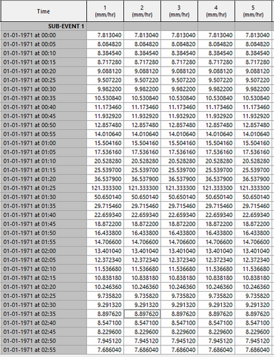
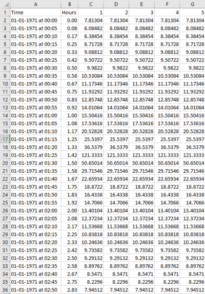
Inflow, level and rainfall boundaries are all held in separate database objects within InfoWorks. These can be exported directly to .csv file format which can then be modified to put it into a TUFLOW format and a bc_dbase file generated to relate the time-varying data to the relevant model node.
InfoWorks ICM Rainfall Time-Varying Data
TUFLOW Rainfall Boundary Time-Varying Data
Exporting a Gridded Ground model
Within InfoWorks, select the gridded ground model, right click and choose Export->to ESRI ASCII grid files. This will export into a file format that can be directly used within TUFLOW.
Other Considerations
- Shapefile limitations mean that field names and values can only be 11 characters long. This can mean that some node ids and other information is truncated. This is reported in the error reporting.
