Difference between revisions of "Integrity Tool - Flow Trace Tool"
Jump to navigation
Jump to search
Tuflowduncan (talk | contribs) (Created page with "The flow trace tool creates traces upstream from the selected channel, selecting all upstream network objects in the QGIS map window (network lines and network points). <ol>...") |
Tuflowduncan (talk | contribs) |
||
| Line 2: | Line 2: | ||
<ol> | <ol> | ||
| − | <li> Find and select link Pipe15. | + | <li> Find and select link Pipe15.<br> |
[[File:Pipe15.png]] | [[File:Pipe15.png]] | ||
| Line 12: | Line 12: | ||
[[File:Flow trace.png]]<br> | [[File:Flow trace.png]]<br> | ||
| − | Table 1 describes the various Checks that can be conducted. | + | Table 1 describes the various Checks that can be conducted.<br> |
| + | <br> | ||
'''Table 1: Flow Trace Checks''' | '''Table 1: Flow Trace Checks''' | ||
| Line 18: | Line 19: | ||
! style="background-color:#005581; font-weight:bold; color:white;"| Check | ! style="background-color:#005581; font-weight:bold; color:white;"| Check | ||
| − | ! style="background-color:#005581; font-weight:bold; color:white;" width= | + | ! style="background-color:#005581; font-weight:bold; color:white;" width=75% | Description |
|- | |- | ||
|Flow Area Check || Identifies location where the downstream flow are decreases | |Flow Area Check || Identifies location where the downstream flow are decreases | ||
| Line 28: | Line 29: | ||
|Ground Cover Check || Identifies locations where the distance between the pipe suffix and the ground elevation (taken from an in input DTM) is less than specified | |Ground Cover Check || Identifies locations where the distance between the pipe suffix and the ground elevation (taken from an in input DTM) is less than specified | ||
|} | |} | ||
| + | |||
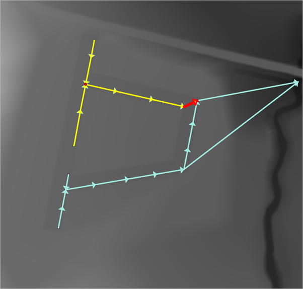
| + | <li> Run the Flow Trace. This will select all the upstream links and also add another output layer identifying the locations which fail the flow area and invert checks.<br> | ||
| + | |||
| + | [[File:Flow trace output.png]]<br> | ||
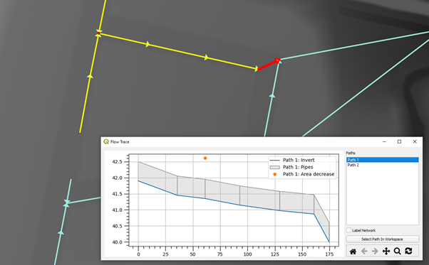
| + | A Flow Trace window is also provided which provides long sections or the various upstream paths from the selected link, highlighting areas of continuity failures. The individual paths can be assessed individually and identify in the canvas.<br> | ||
| + | [[File:Flow trace canvas.png]]<br> | ||
| + | In this instance the identified issues would have to manually adjusted if appropriate, no automatic fixes are available. | ||
Revision as of 22:56, 8 April 2022
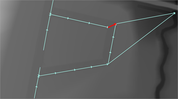
The flow trace tool creates traces upstream from the selected channel, selecting all upstream network objects in the QGIS map window (network lines and network points).
- Find and select link Pipe15.
- Ensure that 1d_nwk_MI01_Pipes_001_L_EG1_ID1_SN1_PD1 is referenced in the 1D network Line Layers and select the Flow Trace tab.
- Select to undertake the Flow Area and the Invert Checks.
- Also ensure the ‘Generate Long plots’ option is selected.
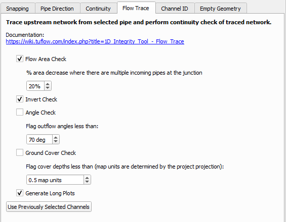
Table 1 describes the various Checks that can be conducted.
Table 1: Flow Trace ChecksCheck Description Flow Area Check Identifies location where the downstream flow are decreases Invert Check Identifies location where pipes have either an adverse gradient or where the outgoing pipe invert level is higher than the incoming pipe invert. Angle Check Identify locations where the angle between incoming and outgoing pipe is less than a given input angle (180 degrees is straight) Ground Cover Check Identifies locations where the distance between the pipe suffix and the ground elevation (taken from an in input DTM) is less than specified - Run the Flow Trace. This will select all the upstream links and also add another output layer identifying the locations which fail the flow area and invert checks.
A Flow Trace window is also provided which provides long sections or the various upstream paths from the selected link, highlighting areas of continuity failures. The individual paths can be assessed individually and identify in the canvas.
In this instance the identified issues would have to manually adjusted if appropriate, no automatic fixes are available.


