Difference between revisions of "TUFLOW HR Output"
| Line 49: | Line 49: | ||
=Water Level Interpolation Method= | =Water Level Interpolation Method= | ||
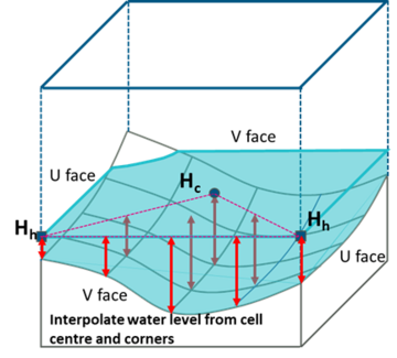
| − | + | The corner water level interpolation methods for the standard output (Map Output Corner Interpolation ==) applies a minimum corner water level of “corner elevation + cell wet/dry depth” if all the surrounding 4 cells are wet. However, this may produce “bumpy” water level outputs along narrow streams in a direct rainfall SGS model between sheet flow cells and fully wet cells when using the new high resolution output. This is caused by applying a linear water level interpolation between SGS cells that have a non-linear minimum SGS elevation as illustrated below. | |
interpolated from the surrounding SGS sampled elevations. | interpolated from the surrounding SGS sampled elevations. | ||
Revision as of 13:01, 20 February 2024
Page Under Construction
Introduction
High Resolution (HR) Grid/Raster Map Outputs was first introduced in TUFLOW 2020-10-AB release. When an SGS model uses “SGS Approach == Method C”, the sampled elevations are retained at the end of the geometry processing. These sub-grid elevations include topography modifiers such as breaklines, and they allow a high-resolution elevation check file to be written and used for high resolution depth map outputs. Currently, ASC, FLT and TIF raster formats are supported.
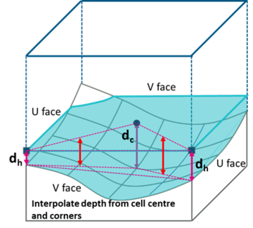
For the HR output the water level at each HR output location is interpolated from the computed 2D water levels. The depth is the difference between the interpolated water level and the sub-grid elevation. This differs from the standard depth output which calculates the depths at cell centres and corners first, then interpolate the depths to the standard output grid locations(default is half the cell size). The difference in the interpolation process is illustrated below.
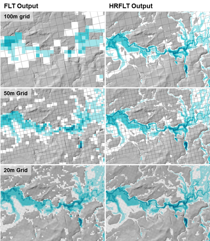
The advantage of the HR output is that it can retain the sub-grid detail of the terrain information even at coarse cell size. As compared in the example below, the HR depth output shows clear flow path even at 100m grid. However, nicer depth output does not mean reliable hydraulic result. In fact, the 100m cell size is too coarse to produce reliable/converged hydraulic results for any real-world flood model. It's is strongly recommended that the model convergence/benchmarking tests must be conducted based on the standard map output, and the HR output should be used for presentation purpose only.
Enable High Resolution Output
To produce high-resolution output, add “HRASC”, “HRFLT” or “HRTIF” to the “Map Output Format ==” command, for example:
Map Output Format == XMDF TIF HRTIF
At the moment, only water level and depth are supported as the High Resolution Output formats, i.e.:
HRTIF Map Output Data Types == h d
The map output data types and output interval can be defined separately for the High Resolution Output formats. For example:
Map Output Interval == 600 ! Sets all map output interval to 600 seconds
HRTIF Map Output Interval == 3600 ! Sets HR map output interval to 3600 seconds
The output resolution for high resolution grid output is defined using the following .tcf command:
HR Grid Output Cell Size == 0.5 ! m or ft
If this command is omitted, the default output resolution is set as the SGS sampling distance.
HR outputs are supported by HPC and Quadtree Output Zones. Below is an example of tcf commands to set up HR output in a output zone:
Model Output Zones == ZoneA

Define Output Zone == ZoneA
   Read GIS Output Zone == ..\model\gis\2d_oz_S05_002_R.shp
   Write Check Files INCLUDE == dem_Z ! includes only dem_Z check file for this output zone
   Map Output Format == HRTIF
   HRFLT Map Output Data Types == h d
   HRFLT Map Output Interval == 3600
   HR Grid Output Cell Size == 0.5
End Define
If HR output is defined in the Map Output Format, a high-resolution DEM_Z check file (DEM_Z_HR) is produced instead of the DEM_Zmin check file.
Water Level Interpolation Method
The corner water level interpolation methods for the standard output (Map Output Corner Interpolation ==) applies a minimum corner water level of “corner elevation + cell wet/dry depth” if all the surrounding 4 cells are wet. However, this may produce “bumpy” water level outputs along narrow streams in a direct rainfall SGS model between sheet flow cells and fully wet cells when using the new high resolution output. This is caused by applying a linear water level interpolation between SGS cells that have a non-linear minimum SGS elevation as illustrated below.
interpolated from the surrounding SGS sampled elevations.
- under construction
Interpolation near Thin Breakline
- under construction
Interpolation for Sheet Flow
- under construction
Any further questions please email TUFLOW support: support@tuflow.com
| Up |
|---|


