Difference between revisions of "Tutorial M03 GIS Inputs QGIS GPKG"
Jump to navigation
Jump to search
(→Method) |
(→Method) |
||
| Line 40: | Line 40: | ||
<li>The 1d_nwk layer represents culverts placed under the road embankments crossing the flow paths. See Table 5-3 of the <u>[https://downloads.tuflow.com/_archive/TUFLOW/Releases/2018-03/TUFLOW%20Manual.2018-03.pdf 2018 TUFLOW Manual]</u> for more information on the attributes.<br> | <li>The 1d_nwk layer represents culverts placed under the road embankments crossing the flow paths. See Table 5-3 of the <u>[https://downloads.tuflow.com/_archive/TUFLOW/Releases/2018-03/TUFLOW%20Manual.2018-03.pdf 2018 TUFLOW Manual]</u> for more information on the attributes.<br> | ||
<br> | <br> | ||
| − | [[File: | + | [[File:Animation_M03_GPKG_GIS_01a.gif]]<br> |
<br> | <br> | ||
Revision as of 11:05, 8 June 2023
Page Under Construction
Introduction
QGIS is used to create, import and view input data.
TUFLOW Project Re-Configuration
Re-configure the TUFLOW project to use and save empty files to the correct folder:
- Go to Plugins > TUFLOW > Editing > Configure / Create TUFLOW Project.
- Change the folder which contains TUFLOW to the Module_03 folder. This is the only change required, the model folder structure and template empty files are supplied from previous model.
Note: The 'results' and 'check' folder get automatically created when the TUFLOW model is run.
- Click 'OK' and save the workspace by selecting Project > Save As.
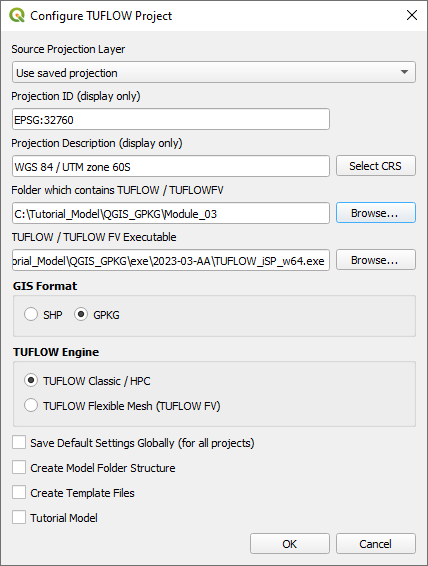
- Set the workspace projection to EPSG:32760, see Set the Projection.

Method
Set up the GeoPackage Database:
- Navigate to the Module_03\TUFLOW\model\gis folder. Save a copy of M02_002.gpkg as M03_001.gpkg.
- Within the QGIS Browser Panel, right click on 'Favorites' and select 'Add a Directory...'.
- Navigate to the Module_03 folder and select it.
Within the QGIS Browser Panel, navigate to the Module_03\Tutorial_Data folder. Drag and drop the following layers into the M03_001.gpkg:
- 1d_nwk_M03_culverts_001_L
- 2d_bc_M03_culverts_001_L
- 2d_bc_M03_culverts_001_R
Investigate the supplied files:
- Open the files, either:
- Within the QGIS Browser Panel, navigate to M03_001.gpkg and double click the layers, or
- In File Explorer, drag and drop the M03_001.gpkg into the QGIS workspace and select the layers (hold Ctrl to select multiple).
- Select ‘Apply TUFLOW Styles to Open Layers’.
- Left click the 1d_nwk_M03_culverts_001_L layer and select 'Apply Label to Current Layer'.
- The 1d_nwk layer represents culverts placed under the road embankments crossing the flow paths. See Table 5-3 of the 2018 TUFLOW Manual for more information on the attributes.
- The 2d_bc layers use SX type connection to embed 1D networks into the 2D domain. It removes water out of the upstream cell(s) and deposits water back at the downstream cell(s). Both region and line SX links need a CN (connection) line snapped from the upstream and downstream vertex of the 1D network line to the SX boundary.


Connect the last 1D network culvert to 2D domain:
- Click on the ‘Import Empty File’ tool from the TUFLOW plugin toolbar.
- Select '2d_bc' from the Empty Type list.
- In the Run ID box write: 'M03_culverts_001'.
- Tick the 'Points' Geometry Type.
- In the Spatial Database Options, select 'All to one'. Navigate to the Module_03/TUFLOW/model/gis folder and select M03_001.gpkg. Click Save and hit 'OK'.
- The 2d_bc_M03_culverts_001_P appears in the Layers panel.
- Zoom to the unconnected 1D culvert.
- Enable snapping, it is important the points are snapped to the network line.
- Right click anywhere in the Toolbar panel and tick on the Snapping Toolbar.
- Select the magnet icon 'Enable Snapping' and 'All Layers > Advanced Configuration', an eye icon appears.
- Select the eye icon 'Edit Advanced Configuration' and tick the 1d_nwk_M03_culverts_001_L.
- Right click on the 2d_bc_M03_culverts_001_P and toggle on editing.
- Select 'Add Point Feature'.
- Digitise a point snapped to upstream end and downstream end of the 1d_nwk layer.
- When terminating each point, an attributes dialog is displayed. Enter Type as 'SX'.
- Turn off editing to save the edits.
- The point SX connection selects a single cell at the upstream and downstream of the 1d_nwk layer.

Conclusion
- 1D network culverts were set up and connected to the 2D domain with 1D/2D links.
| Up |
|---|