Tutorial M05 GIS Inputs QGIS GPKG
Revision as of 15:27, 8 June 2023 by Emilie Nielsen (talk | contribs) (→TUFLOW Project Re-Configuration)
Page Under Construction
Introduction
QGIS is used to create, import and view input data.
TUFLOW Project Re-Configuration
Re-configure the TUFLOW project to use and save empty files to the correct folder:
- Go to Plugins > TUFLOW > Editing > Configure / Create TUFLOW Project.
- Change the folder which contains TUFLOW to the Module_05 folder. This is the only change required, the model folder structure and template empty files are supplied from previous model.
Note: The 'results' and 'check' folder get automatically created when the TUFLOW model is run.
- Click 'OK' and save the QGIS workspace by selecting Project > Save As.
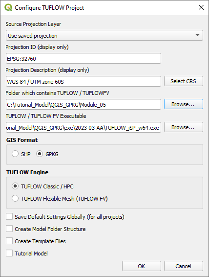
- Set the QGIS workspace projection to EPSG:32760, see Set the Projection.

Method
Navigate to the Module_05\Tutorial_Data folder. Copy and save all the below layers into the Module_05\TUFLOW\model\gis folder:
- 1d_nwk_M05_pipes_001_L
- 1d_nwk_M05_pits_001_P
- 2d_sa_M05_001_R
- 2d_zsh_M02_landscape_002_L
- 2d_zsh_M02_landscape_002_P
- 2d_zsh_M02_landscape_002_R
- 2d_mat_M02_landscape_002_R
Investigate the supplied files:
- Open the files, either:
- Drag and drop all .shp files into the QGIS workspace, or
- Select Layer > Add layer > Add Vector Layer and navigate to the Module_05\TUFLOW\model\gis folder.
- The 2d_zsh landscape files create a TIN elevation footprint of the development. The 2d_mat file contains polygons that represent the updated land use due to the topography changes. See Module 2 for more information.
- The 1d_nwk layers represents pits and pipes. The pipes are a series of circular culverts with a set Manning’s roughness value. The pits are set up as a series of Q type pits to convey flow into the pipe network via SX connections. See Section 5.4 of the 2018 TUFLOW Manual for more information on the attributes.

Create outlet from the 1D pipe network into the 2D domain with the TUFLOW plugin:
- It is recommended to have a grd_check file from a previous run (with the same model cell size) turned on when digitising SX lines as the number of cells selected must correspond to the dimensions of the 1D structure. In this module, the outlet pipe has a diameter of 0.9m, only one cell is selected.
- Click on the ‘Import Empty File’ symbol from the TUFLOW plugin toolbar.
- Select '2d_bc' from the Empty Type list.
- In the Run ID box write 'M05_outlet_001'.
- Tick the 'Lines' Geometry Type and hit 'OK'. The 2d_bc layer appears in the QGIS Layers panel.
- Right click on the 2d_bc_M05_outlet_001_L and toggle on Editing.
- Enable snapping and use the 'Edit Advanced Configuration' tool to select 2d_bc_M05_outlet_001_L and 1d_nwk_M05_pipes_001_L.
- Select 'Add Line Feature' and digitise a line snapped from the downstream end of the pipe.
- Terminate the line by right clicking and write 'CN' (connection) into the 'Type' attribute.
- Add another line snapped to the end of the CN line and enter 'SX' as the 'Type' attribute to allow flow to transfer from 1D to 2D.
- Turn off editing to save the edits.

Investigate the supplied inflows:
- The 2d_sa layer contains four regions, each with a different name attribute to apply unique inflows to different parts of the development site:

Conclusion
- The 1d_nwk pipes and pits files were supplied and investigated.
- An outlet from the pipe network was digitised downstream of the road as 2d_bc.
- The 2d_sa files were supplied to apply inflow directly to the pits.
| Up |
|---|