Tutorial M10
Introduction
In this module, five ways of modelling dam break are introduced:
- Part 1: 2D Variable Geometry Time Trigger - the dam break begins at 1 hour and develops over 15 minutes.
- Part 2: 2D Variable Geometry Water Level Trigger - the dam break begins when the water level at a point is triggered.
- Part 3: 1D Piping Failure and 1D Dam Failure - introduces the TUFLOW Operations Control file (TOC).
- Part 4: Boundary Condition Breach Hydrograph - the dam break is modelled using an input dam break hydrograph.
- Part 5: Non-Newtonian - Part 4 using Non-Newtonian fluid properties.
The GIS layers are:
- TGC layers:
- 2d_zsh: A layer used to modify Zpt elevations using points and lines.
- 2d_vzsh: A layer used to modify Zpt elevations over time to simulate breaking of embankments.
- TCF layers:
- 2d_iwl: A layer used to set 2D initial water levels spatially.
- TBC layers:
- 2d_sa: A layer used to apply a flow versus time hydrograph to simulate a breach condition.
- 2d_bc: A layer used to apply a head vs flow (stage-discharge) boundary - used as the downstream boundary.
- ECF layers:
- 1d_nwk: A layer used to define the 1D piping failure and 1D dam failure.
Module 10 builds from the model created in Module 2. The completed Module 2 model is provided in the Module_10\TUFLOW folder.
Part 1 - 2D Variable Geometry Time Trigger
Simulate a simple form of dam break using a time trigger.
GIS Inputs
Create, import and view input data:
Simulation Control Files
TUFLOW Geometry Control File (TGC)
- Save a copy of M02_001.tgc as M10_001.tgc in the Module_10\TUFLOW\model folder.
- Open the M10_001.tgc in a text editor.
- Include the following commands after the Read GIS Z Shape == gis\2d_zsh_M02_rd_crest_001_L.shp | gis\2d_zsh_M02_rd_crest_001_P.shp command:
Read GIS Z Shape == gis\2d_zsh_M10_damwall_001_L.shp ! Creates dam embankment
Read GIS Variable Z Shape == gis\2d_vzsh_M10_dambreak_001_R.shp ! Creates dam break - Save the TGC.
TUFLOW Boundary Control File (TBC)
- Save a copy of M01_001.tbc as M10_001.tbc in the Module_10\TUFLOW\model folder.
- Open the M10_001.tbc in a text editor.
- Update the reference to the 2D boundaries:
Read GIS BC == gis\2d_bc_M10_001_L.shp
- Include a reference to the new 2D source area boundary:
Read GIS SA == gis\2d_sa_M10_inflow_001_R.shp ! Reads in 2D source area boundaries
- Save the TBC.
TUFLOW Control File (TCF)
- Save a copy of M02_5m_001.tcf as M10_5m_001.tcf in the Module_10\TUFLOW\runs folder.
- Open the M10_5m_001.tcf in a text editor and update the reference of the TGC:
Geometry Control File == ..\model\M10_001.tgc ! Reference the TUFLOW Geometry Control File
- Update the reference of the TBC:
BC Control File == ..\model\M10_001.tbc ! Reference the TUFLOW Boundary Conditions Control File
- An Initial Water Level command is required. Include the following command after the 'Model Inputs' section:
! INITIAL WATER LEVEL
Read GIS IWL == ..\model\gis\2d_iwl_M10_001_R.shp ! Reads in initial water level
- Add bathymetry (ZH) as additional Map Output Data Type:
Map Output Data Types == h V d dt ZH ! Outputs water levels, velocities, depths, minimum timestep, bathymetry
- Save the TCF.
Running the Simulation
- Save a copy of _run_M02_HPC.bat as _run_M10_HPC.bat in the Module_10\TUFLOW\runs folder.
- Update the batch file to reference the M10_5m_001.tcf :
set exe="..\..\..\exe\2023-03-AA\TUFLOW_iSP_w64.exe"
set run=start "TUFLOW" /wait %exe% -b
%run% M10_5m_001.tcf
- Save the batch file and double click it in file explorer to run the simulation.
Troubleshooting
See tips on common mistakes and troubleshooting steps if the model doesn't run:
Check Files
While the model is running, review the added features are specified correctly:
Results
When the model is finished, review the results:
Part 2 - 2D Variable Geometry Water Level Trigger
Simulate a simple form of dam break using a water level trigger.
Part 2 builds from the model created in Part 1.
GIS Inputs
Create, import and view input data:
Simulation Control Files
TUFLOW Geometry Control File (TGC)
- Save a copy of M10_001.tgc as M10_002.tgc in the Module_10\TUFLOW\model folder.
- Open the M10_002.tgc in a text editor.
- Update the reference to the Variable Z Shape:
Read GIS Variable Z Shape == gis\2d_vzsh_M10_dambreak_002_R.shp | gis\2d_vzsh_M10_dambreak_002_P.shp ! Creates dam break - Save the TGC.
TUFLOW Control File (TCF)
- Save a copy of M10_5m_001.tcf as M10_5m_002.tcf in the Module_10\TUFLOW\runs folder.
- Open the M10_5m_002.tcf in a text editor and update the reference of the TGC:
Geometry Control File == ..\model\M10_002.tgc ! Reference the TUFLOW Geometry Control File
- Save the TCF.
Running the Simulation
- Open _run_M10_HPC.bat in a text editor from the Module_10\TUFLOW\runs folder.
- Update the batch file to reference the M10_5m_002.tcf :
set exe="..\..\..\exe\2023-03-AA\TUFLOW_iSP_w64.exe"
set run=start "TUFLOW" /wait %exe% -b
%run% M10_5m_002.tcf
- Save the batch file and double click it in file explorer to run the simulation.
Troubleshooting
See tips on common mistakes and troubleshooting steps if the model doesn't run:
Check Files
While the model is running, review the added features are specified correctly:
Results
When the model is finished, review the results:
Part 3 - 1D Piping Failure and 1D Dam Failure
Dam breaks can be triggered by flow overtopping, as well as internal erosion (often called piping) when water seepages through the embankment forming a small flowpath. Simulate a 1D piping failure that transitions to a 1D dam failure - trapezoidal cross section failure using a 1D operational channel.
Part 3 builds from the model created in Part 1.
1D Piping Failure:

1D Dam Failure:

GIS Inputs
Create, import and view input data:
Simulation Control Files
TUFLOW Operations Control (TOC)
- Navigate to the Module_10\Tutorial_Data folder. Copy the M10_003.toc into the Module_10\TUFLOW\model folder. This file contains the commands specific to the operational controls.
- Open the M10_003.toc. A summary of the defining logic blocks:
- Pipe Failure control commands contained within the 'Define Pipe Failure Control == PF01' logic block:
- The piping failure is triggered when the water level at the upstream node of the 1d_nwk PF01 line is greater than 59.5m.
- The piping failure takes 0.5 hours to reach it's full extent (defined by the width and height attributes in the 1d_nwk layer).
- Once the piping failure reaches it's full extent, it takes 60 seconds to collapse.
- The default shape of the piping failure is rectangular.
- The discharge coefficient (Cd) is set to 0.6.
- Dam Failure control commands contained within the 'Define Dam Failure Control == DF01' logic block:
- The dam failure is triggered when the pipe failure at PF01 reaches 99.9% complete.
- An initial collapse to a depth of 3m occurs within 60 seconds.
- Following the initial collapse the dam fails in a trapezoidal shape, with a side slope of 60 degrees, to a depth of 20 metres and a top width fully breached of 25 metres over a period of 0.5 hours. The top width fully breached can be set smaller than the 'Width_or_Dia' attribute if the maximum breach width does not reach the total width of the dam crest.
TUFLOW Estry Control File (ECF)
A new control file, the ESTRY Control File (ECF), is introduced. ESTRY is TUFLOW’s 1D hydraulic solver and includes all of the 1D files and commands.
- Create a new text file M10_003.ecf in the Module_10\TUFLOW\model folder.
- Add the following command lines:
! 1D TIME CONTROL
Timestep == 0.5 ! Specifies a 1D computational timestep as 0.5 seconds
! MODEL INPUTS
Read Operating Controls File == ..\model\M10_003.toc ! Reference the TUFLOW Operations Control File
! 1D PIPING FAILURE
Read GIS Network == gis\1d_nwk_M10_piping_003_L.shp ! Defines 1D piping failure
! 1D DAMBREAK
Read GIS Network == gis\1d_nwk_M10_dambreak_003_L.shp ! Defines 1D dambreak
- Save the ECF.
TUFLOW Geometry Control File (TGC)
- Save a copy of M10_001.tgc as M10_003.tgc in the Module_10\TUFLOW\model folder.
- Open the M10_003.tgc in a text editor.
- Comment out or delete the reference to the Variable Z Shape, the dam failure is controlled within the ECF and TOC files:
! Read GIS Variable Z Shape == gis\2d_vzsh_M10_dambreak_001_R.shp - Save the TGC.
TUFLOW Boundary Control File (TBC)
- Save a copy of M01_001.tbc as M10_003.tbc in the Module_10\TUFLOW\model folder.
- Open the M10_003.tbc in a text editor.
- Include a reference to the new 1D/2D boundary:
! INTERNAL 1D/2D BOUNDARIES
Read GIS BC == gis\2d_bc_M10_piping_dambreak_003_L.shp ! Links the 1D piping and dambreak to the 2D domain
- Save the TBC.
TUFLOW Control File (TCF)
- Save a copy of M10_5m_001.tcf as M10_5m_003.tcf in the Module_10\TUFLOW\runs folder.
- Open the M10_5m_003.tcf in a text editor.
- Include a reference of the ECF in the 'Model Inputs' section:
ESTRY Control File == ..\model\M10_003.ecf ! Reference the ESTRY (1D) Control File File
- Update the reference of the TGC:
Geometry Control File == ..\model\M10_003.tgc ! Reference the TUFLOW Geometry Control File
- Update the reference of the TBC:
BC Control File == ..\model\M10_003.tbc ! Reference the TUFLOW Boundary Conditions Control File
- Save the TCF.
Running the Simulation
- Open _run_M10_HPC.bat in a text editor from the Module_10\TUFLOW\runs folder.
- Update the batch file to reference the M10_5m_003.tcf :
set exe="..\..\..\exe\2023-03-AA\TUFLOW_iSP_w64.exe"
set run=start "TUFLOW" /wait %exe% -b
%run% M10_5m_003.tcf
- Save the batch file and double click it in file explorer to run the simulation.
Troubleshooting
See tips on common mistakes and troubleshooting steps if the model doesn't run:
Check Files
While the model is running, review the added features are specified correctly:
Review the 1D output file:
- Open the M10_5m_003.eof from the Module_10\TUFLOW\results folder in a text editor.
- Review the 1D Dam Failure Coefficients and Culvert and Pipe Data:
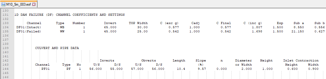

Results
When the model is finished, review the results:
Review the Operational structure time-series data:
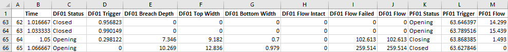
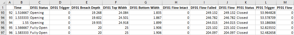
- Open the M10_5m_003_1d_O.csv from the Module_10\TUFLOW\results\csv folder.
- The file reports the time varying status of the pipe and dam failure, and the resulting flows and dimensions:
- The dam failure is triggered by the percent completion of the pipe failure, it begins when the pipe failure ends.
- The 'Flow Intact' column is flow overtopping the dam that occurs before the dam break, in this example the dam does not overtop. The 'Flow Failed' column is the flow during and after the dam break.
- After approximately 1.5 hours the dam failure is 'Fully Open', the 'Breach Depth' is 20m, 'Top Width' is 25m, 'Bottom Width' is 1.9m.
- After approximately 1.5 hours the dam failure is 'Fully Open', the 'Breach Depth' is 20m, 'Top Width' is 25m, 'Bottom Width' is 1.9m.


Part 4 - Boundary Condition Breach Hydrograph
Simulate a dam break using an inflow hydrograph. All other inflows are removed from the model.
Part 4 builds from the model created in Part 1.
GIS Inputs
Create, import and view input data:
Simulation Control Files
TUFLOW Geometry Control File (TGC)
- Save a copy of M10_001.tgc as M10_004.tgc in the Module_10\TUFLOW\model folder.
- Open the M10_004.tgc in a text editor.
- Comment out or delete the reference to the Variable Z Shape:
! Read GIS Variable Z Shape == gis\2d_vzsh_M10_dambreak_001_R.shp - Save the TGC.
TUFLOW Boundary Control File (TBC)
- Save a copy of M10_001.tbc as M10_004.tbc in the Module_10\TUFLOW\model folder.
- Open the M10_004.tbc in a text editor.
- Comment out or delete the reference to the upstream 2d_sa inflow and internal 2d_sa inflows representing the four flows on the internal catchments, the module is simulating flow from the dam break only:
! Read GIS SA == gis\2d_sa_M01_001_R.shp
! Read GIS SA == gis\2d_sa_M10_inflow_001_R.shp
- Include a reference to the new 2D source area boundary representing the flow from the dam break:
Read GIS SA == gis\2d_sa_M10_dambreak_004_R.shp ! Reads in 2D source area boundaries
- Save the TBC.
TUFLOW Boundary Condition Database (bc_dbase)
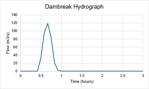
Update the bc_dbase with a reference to the dam break hydrograph:
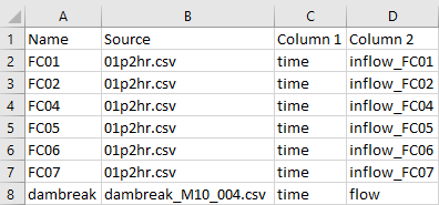
- Navigate to the Module_10\Tutorial_Data folder. Copy the dambreak_M10_004.csv into the Module_10\TUFLOW\bc_dbase folder. This file contains the dam break hydrograph applied at the 2d_sa polygon.
- Save a copy of bc_dbase.csv as bc_dbase_M10_004.csv in the Module_10\TUFLOW\bc_dbase folder.
- Open the bc_dbase_M10_004.csv file and add the additional inflow data to row 8:
- Save the bc_dbase.


TUFLOW Control File (TCF)
- Save a copy of M10_5m_001.tcf as M10_5m_004.tcf in the Module_10\TUFLOW\runs folder.
- Open the M10_5m_004.tcf in a text editor.
- Update the reference of the TGC:
Geometry Control File == ..\model\M10_004.tgc ! Reference the TUFLOW Geometry Control File
- Update the reference of the TBC:
BC Control File == ..\model\M10_004.tbc ! Reference the TUFLOW Boundary Conditions Control File
- Update the reference of the bc_dbase:
BC Database == ..\bc_dbase\bc_dbase_M10_004.csv ! Reference the Boundary Conditions Database
- A Timestep Maximum command is required in some dam break models to ensure the timestep does not get too large during periods where cells are dry (causing the model to become unstable). Include the command in the 'Time Control' section:
Timestep Maximum == 2 ! Specifies a maximum timestep of 2 seconds
- Comment out or delete the reference to the Initial Water Level:
! Read GIS IWL == ..\model\gis\2d_iwl_M10_001_R.shp ! Reads in initial water level - Save the TCF.
Running the Simulation
- Open _run_M10_HPC.bat in a text editor from the Module_10\TUFLOW\runs folder.
- Update the batch file to reference the M10_5m_004.tcf :
set exe="..\..\..\exe\2023-03-AA\TUFLOW_iSP_w64.exe"
set run=start "TUFLOW" /wait %exe% -b
%run% M10_5m_004.tcf
- Save the batch file and double click it in file explorer to run the simulation.
Troubleshooting
See tips on common mistakes and troubleshooting steps if the model doesn't run:
Check Files
While the model is running, review the added features are specified correctly:
Results
When the model is finished, review the results:
Part 5 - Non-Newtonian
TUFLOW supports the modelling of Non-Newtonian fluids. It is a fluid that does not follow Newton's law of viscosity (i.e. constant viscosity independent of stress). The viscosity can change when under force to behave either more liquid or more solid. This can occur in a dam break due to the sediment contained within the dam.
For more information, see Section 5.4 of the latest Release Notes and watch the Tsunami and Dam Failure and Non-Newtonian Modelling video (from 36 minutes).
Part 5 builds from the model created in Part 4.
Simulation Control Files
TUFLOW Control File (TCF)
- Save a copy of M10_5m_004.tcf as M10_5m_005.tcf in the Module_10\TUFLOW\runs folder.
- Open the M10_5m_005.tcf in a text editor.
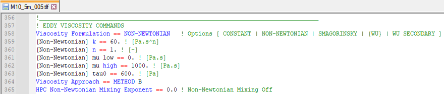
- Include the following commands to turn on the Non-Newtonian viscosity formulation and specify the viscosity coefficients, at the end of the TCF:
! NON-NEWTONIAN
Viscosity Formulation == Non-Newtonian ! Specifies Non-Newtonian viscosity formulation
Viscosity Coefficients == 60, 1, 0, 1000, 600 ! Specifies viscosity coefficients: k, n, muLow, muHigh, tau0
Where:- k: viscosity coefficient (Pa.s^n)
- 𝑛: shear thickening exponent, must be non zero and positive (shear thinning fluids exhibit 𝑛 < 1, shear thickening 𝑛 > 1, and Newtonian fluids 𝑛 = 1)
- muLow: lower viscosity limit (Pa.s)
- muHigh: higher viscosity limit (Pa.s)
- tau0: shear yield stress (Pa)
- Save the TCF.
Running the Simulation
- Open _run_M10_HPC.bat in a text editor from the Module_10\TUFLOW\runs folder.
- Update the batch file to reference the M10_5m_005.tcf:
set exe="..\..\..\exe\2023-03-AA\TUFLOW_iSP_w64.exe"
set run=start "TUFLOW" /wait %exe% -b
%run% M10_5m_005.tcf
- Save the batch file and double click it in file explorer to run the simulation.
Troubleshooting
See tips on common mistakes and troubleshooting steps if the model doesn't run:
Check Files
While the model is running, review the added features are specified correctly:
- Open the M10_5m_005.tlf from the Module_10\TUFLOW\runs\log folder in a text editor.
- Search for 'Viscosity Formulation' and review the input values:

Results
When the model is finished, review the results:
Conclusion
- A dam break was modelled using five methods - time trigger, water level trigger, 1D piping and dam failure using a TUFLOW Operations Control (TOC), using an inflow hydrograph and with Non-Newtonian flow.
- Non-Newtonian flow was modelled and results compared to Newtonian flow.
- TUFLOW log files and GIS layers were used to check the dam break was modelled correctly.
- New bathymetry map output and 1D operational structure time series data were inspected.
| Up |
|---|