Tute M04 SMS 2d bc hx Archive
In this section we will create the 1D/2D links for the open channel. As described on the previous page, this consists of a 1D/2D link with type "HX" and a series of connection lines that connect the 1D computation points to the HX line. For this tutorial the HX lines have been provided.
This set up involve two processes:
Create HX lines
- Select File | Open. Browse and open file \Module_Data\Module04\2d_bc_M04_HX_001.shp. This shapefile has several lines which we will use to define the location of HX lines.
- Turn off the display of all other coverages except BC and Cross_Sections coverages.
- Click on BC coverage to make it active. Then click on Create Feature Arc tool.
- With the shapefile 2d_bc_M04_HX_001.shp as guide, trace the HX lines.
- Make sure to start and end the HX line tracing at a location where we will create a CN connection. In this case our CN connections will be at the exact same locations as the cross sections. Thus, begin and end the HX lines at a cross section.
- Make sure that the HX lines snap to the edges of cross section arcs and boundary polygon (you do not need to end the arc at the cross sections, you just need them snapped).
- Notice that there is break in the HX lines where the culverts are defined. That means if any overflow occurs near the culverts, that will be handled by 2D model (area enclosed inside the polygons formed by these HX lines will be deactivated from the 2D domain and 1D flow equations will be applied).
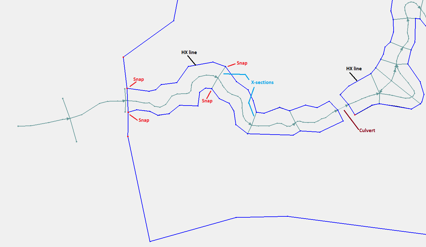
- Once you have created all the HX arcs (See image below), click on Select Feature Arc tool and double click each of the lines marked as HX in the following image.
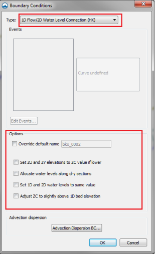
- In the "Boundary Conditions" dialog, change BC type to 1D Flow/2D Water Level Connection (HX). Make sure that none of the other options are turned on. Click OK.


Create CN Connections
There are two parts to defining 1D/2D links. The first is on the 2D domain, and the second is in the 1D domain. We have already defined the flow interfaces between the 1D and 2D domains in the BC coverage as HX lines. TUFLOW associates these arcs with the 2D domain spatially. Along with these HX arcs, we must define the 1D/2D connection from the 1D network nodes. These 1D/2D connection arcs tell TUFLOW which locations along the HX arcs match individual nodes in the 1D network so that the flow interchange can take place at these locations. Since the cross-section arcs are in the same locations as we want to place our 1D/2D connections, we will start with a copy of the cross section coverage.
- In the project explorer, right click on the Cross_Sections coverage and select Duplicate.
- Right click on this new coverage and change it's name to be 1D2D_Connection.
- Right click on 1D2D_Connection coverage and select Type | Models | TUFLOW | 1D/2D Connections.
- Scan through the model domain to make sure that each CN line is extended far enough on each side of the channel to intersect with the HX lines. If they are shorter, select the end node and drag it further. If it is extended beyond the HX lines, leave it like that, we will remove the extra arcs later.
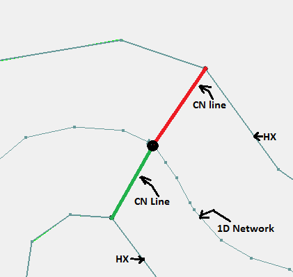
- The CN lines transfer water level from the 1D network to the HX lines on both sides of the channel because of which, there should be two separate lines connecting on either side of the channel, see following figure.
- Make sure that the 1D2D_Connection coverage is active and click on Select Feature Vertex tool.
- Right click on the empty area on the screen and click Select All.
- Right click again and select Convert to Nodes. You should have noticed that all the vertices at the middle of the CN lines connecting with the 1D network are now converted to a nodes thus breaking the lines into two, each segment connecting to the HX lines on opposite bank.
- Note: We already mentioned that the HX lines must snap to these connection arcs (called CN lines). While creating the HX lines in previous steps, we made sure that they snap to the cross sections arcs and since the 1D2D_Connections coverage is a copy of it, the HX lines and the CN arcs are most probably snapped. But since TUFLOW will not produce proper result if this connection is not properly established. SMS has a tool to enfore this connection.
- In the project explorer, right click on 1D2D_Connection coverage and select Clean Connections.
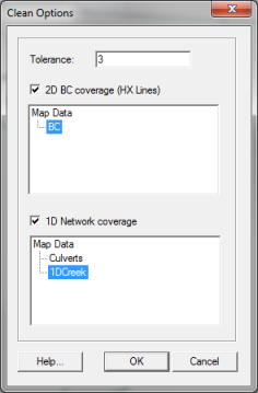
- In Clean Options dialog, change Tolerance to 3m, toggle on 2D BC Coverage (HX Lines) and click on BC. Click OK.
- Toggle on 1D Network Coverage and click on 1DCreek.
This will make sure that connections arcs end at HX boundaries and the HX boundaries have vertices at the connection endpoints. Although there is no visible change in the screen, new vertices will be created, and if needed, the arc end points will be moved.
- As we discussed earlier, the CN arc(s) must snap to the end of 1D_Creek arc. If you zoom in near the area where we defined a weir at a bend, there are CN lines connection on either banks of the river to the weir. Since the 1D arc does not break at that location, the CN arcs cannot be snapped to the 1D_Creek arc. Select and delete both the CN arcs (See the following image)
- Zoom in to the upstream end of the model (lower left corner of the screen). You should see a CN line outside the 1D/2D connection area. Select this line and delete it.
- Similarly, make sure that the second CN line (the once closer to the 2D boundary) is snapped to the HX lines on both sides. If they are not snapped, feel free to move the node/vertex or add a new arc segment.
- As the upstream end of the HX line extends out perpendicular to the flow direction, we want to apply the same water level along this section. This allows water to flow onto the floodplain if the flow exceeds the capacity of the channel. Digitize two more lines from the end of the same channel to the HX line at the top of bank. This is shown in the image below. Note: The shape and position of the CN lines do not matter, their purpose is to establish a connection
- Create similar CN connection at the most downstream end also.
- Delete 5 CN lines counting from the most downstream end.
- With the following image as reference, modify/Add CN lines where 2D domain ends.
- Note: We created these extra CN lines at the two ends of the model because at the upstream end we are letting water to be transferred over the 2D domain if the capacity of channel is exceeded. Similarly, at the downstream end, the 2D domain terminates and any water that is flowing on the 2D domain will be collected back to the 1D network.
- Save the SMS project


Conclusion
We have added the HX lines as well as CN connections to our model. These two lines tell tuflow to send water back and forth in the 1D and 2D domains.
- Note: Unlike other GIS tools, SMS automatically extracts elevations for the HX lines when we export the TUFLOW files. So we will skip the section to define breaklines along the 1D/2d connections.
Let's proceed to another section to deactivate the 2D cells in the creek areas.