Tutorial M05
Introduction
In this module, an integrated urban drainage network is represented.
The GIS layers are:
- TGC layers:
- 2d_zsh: A layer used to modify Zpt elevations using points, lines and polygons.
- 2d_mat: A layer used to define the land use (material) types within the developmental area.
- ECF layers:
- 1d_nwk: A layer used to define pipes and pits in 1D.
- TBC layers:
- 2d_sa: A layer to define internal 2D flow boundaries.
- 2d_bc: A layer defining the locations of external 2D boundaries.
Module 5 builds from the model created in Module 2. The completed Module 2 model is provided in the Module_05\TUFLOW folder.
GIS Inputs
Create, import and view input data:
Boundary Condition Database (bc_dbase)
Update the bc_dbase with a reference of the new 2d_sa regions:
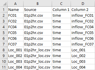
- Navigate to the Module_05\Tutorial_Data folder. Copy the 01p2hr_loc.csv and paste it in the Module_05\TUFLOW\bc_dbase folder. This file contains the inflow data applied to each of the 2d_sa regions.
- Open the file, there are 4 columns labelled ‘Loc_001’ to ‘Loc_004’. These correspond to the names of the 2d_sa regions.
- Save a copy of the bc_dbase.csv as bc_dbase_M05_001.csv.
- Open the file and add the additional inflows:
- Save the bc_dbase.

Note: Direct rainfall can be applied to the model instead of the 2d_sa regions. The pits gather overland flow and convey it into the pipe network. Direct rainfall is covered in Module 6.
Pit Inlet Database (pit_dbase)
The pit inlet database assigns a depth discharge relationship to pit inlet types:
- Create a new folder called pit_dbase in the Module_05\TUFLOW folder.
- Navigate to the Module_05\Tutorial_Data, copy and paste the following csv files into the Module_05\TUFLOW\pit_dbase folder:
- pit_inlet_curves.csv
- pit_inet_dbase.csv
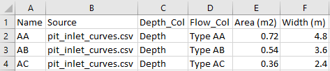
- Open the pit_inlet_dbase. The three different names are user defined inlet types matching the attribute in 1d_nwk pits file. They define the inflow into the pit depending on the above ground water depth and are derived based on the geometry of the pits. These can be unique to every model. From the pit_inlet_dbase, ‘AB’ inlet type has an area of 0.54m2 and width of 3.6m and references the ‘Type AB’ in the flow column from the pit_inlet_curves file.
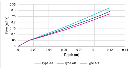
- Open the pit_inlet_curves, it defines the depth discharge relationship for each pit inlet type.
- Plot the depth against flow for each pit type to view the relationship. The curves are the limiting factor for the amount of flow entering the pits.


Note: A spreadsheet InletCurves_SI_Units_001.xls located in the Module_05\Tutorial Dataset folder can be used to derive unique depth discharge curve relationships based on input geometry.
Simulation Control Files
TUFLOW Geometry Control File (TGC)
- Save a copy of M02_001.tgc as M05_001.tgc in the Module_05\TUFLOW\model folder.
- Open the file M05_001.tgc in a text editor and add the additional line below the 'Read GIS Z Shape ' command:
QGIS - SHP
Create TIN Zpts == gis\2d_zsh_M02_landscape_002_R.shp | gis\2d_zsh_M02_landscape_002_L.shp | gis\2d_zsh_M02_landscape_002_P.shp ! Defines areas of complex landscaping
QGIS - GPKG
Create TIN Zpts == 2d_zsh_M02_landscape_002_R | 2d_zsh_M02_landscape_002_L | 2d_zsh_M02_landscape_002_P ! Defines areas of complex landscaping
- Add in the following line after the 'Read GIS Mat ' command.
QGIS - SHP
Read GIS Mat == gis\2d_mat_M02_landscape_002_R.shp ! Sets the material values according to attributes in the GIS layer
QGIS - GPKG
Read GIS Mat == 2d_mat_M02_landscape_002_R ! Sets the material values according to attributes in the GIS layer
Assigns the updated materials values due to the development. - Save the TGC.
The three Z shapes that form the TIN are from Module 2, this is the foundation of the development.
TUFLOW Boundary Control File (TBC)
- Save a copy of M01_001.tbc as M05_001.tbc in the Module_05\TUFLOW\model folder.
- Open the file M05_001.tbc in a text editor and add the following two commands:
QGIS - SHP
Read GIS SA PITS == gis\2d_sa_M05_001_R.shp ! Reads in 2D boundaries directly to 1D pits
Read GIS BC == gis\2d_bc_M05_outlet_001_L.shp ! Reads in 2D boundaries from 1D network
QGIS - GPKG
Read GIS SA PITS == 2d_sa_M05_001_R ! Reads in 2D boundaries directly to 1D pits
Read GIS BC == 2d_bc_M05_outlet_001_L ! Reads in 2D boundaries from 1D network
- Save the TBC.
The command ‘Read GIS SA PITS’ directs the inflow to 2D cells connected to the 1D pits with 'SX' as 'Conn_1D_2D' attribute and it spreads the inflow equally over the cells containing pits. The ‘Read GIS BC’ command defines the outlet of the pipe network.
ESTRY Control File (ECF)
- Create a new text file called M05_001.ecf and save it in the Module_05\TUFLOW\model folder.
- Add the following command lines:
QGIS - SHP
Timestep == 0.5 ! Specifies a 1D computational timestep as 0.5 seconds
Read GIS Network == gis\1d_nwk_M05_pipes_001_L.shp ! Defines pipes
Read GIS Network == gis\1d_nwk_M05_pits_001_P.shp ! Defines pits
Pit Inlet Database == ..\pit_dbase\pit_inlet_dbase.csv ! Pit inlet database defining depth-discharge curves
QGIS - GPKG
Timestep == 0.5 ! Specifies a 1D computational timestep as 0.5 seconds
Read GIS Network == 1d_nwk_M05_pipes_001_L ! Defines pipes
Read GIS Network == 1d_nwk_M05_pits_001_P ! Defines pits
Pit Inlet Database == ..\pit_dbase\pit_inlet_dbase.csv ! Pit inlet database defining depth-discharge curves
- Save the ECF.
The above sets a 1D computational timestep of 0.5 seconds, reads in both the pipes and the pits 1d_nwk files and links these to the pit inlet database.
TUFLOW Control File (TCF)
- Save a copy of M02_5m_001.tcf as M05_5m_001.tcf in the Module_05\TUFLOW\runs folder.
- Open the file M05_5m_001.tcf in a text editor and add the following line:
ESTRY Control File == ..\model\M05_001.ecf ! Reference the ESTRY (1D) Control File
- Make the following reference updates:
QGIS - SHP
Geometry Control File == ..\model\M05_001.tgc ! Reference the TUFLOW Geometry Control File
BC Control File == ..\model\M05_001.tbc ! Reference the TUFLOW Boundary Conditions Control File
BC Database == ..\bc_dbase\bc_dbase_M05_001.csv ! Reference the Boundary Conditions Database
QGIS - GPKG
Spatial Database == ..\model\gis\M05_001.gpkg ! Specify the location of the GeoPackage Spatial Database
Geometry Control File == ..\model\M05_001.tgc ! Reference the TUFLOW Geometry Control File
BC Control File == ..\model\M05_001.tbc ! Reference the TUFLOW Boundary Conditions Control File
BC Database == ..\bc_dbase\bc_dbase_M05_001.csv ! Reference the Boundary Conditions Database
- Save the TCF.
Running the Simulation
- Save a copy of _run_M02_HPC.bat as _run_M05_HPC.bat in the Module_05\TUFLOW\runs folder.
- Update the batch file to reference the M05_5m_001.tcf :
set exe="..\..\..\exe\2023-03-AA\TUFLOW_iSP_w64.exe"
set run=start "TUFLOW" /wait %exe% -b
%run% M05_5m_001.tcf
- Save the batch file and double click it in file explorer to run the simulation.
Troubleshooting
See tips on common mistakes and troubleshooting steps if the model doesn't run:
Check Files
While the model is running, review the added features are specified correctly:
Results
When the model is finished, review the results:
Conclusion
- 1D underground pipes and pits were provided and added to the model discharging into the 2D domain.
- Check files were used to review the connection between the pipe network and the 2D domain.
- Results were viewed to assess the amount of water in the pipe network.
- 1D underground pipes and pits were provided and added to the model discharging into the 2D domain.
1D Integrity Tool (Optional)
The 1D Integrity Tool is a suite of tools designed to help modellers find and fix potential errors in 1D networks prior to running TUFLOW. It is a free tool that comes as part of the TUFLOW plugin:
| Up |
|---|