FM Tutorial M02 QGIS GPKG Flood Modeller1D/ESTRY 1D Link
Introduction
This page describes the method in QGIS for linking TUFLOW 1D ESTRY networks to a 1D river channel represented within Flood Modeller. Firstly, a pipe network represented in ESTRY will be linked to Flood Modeller using an "X1DH" link. The Flood Modeller 1D network will then be extended downstream by connecting it to an ESTRY river network using an "X1DQ" link.
Method
- Open the layers 1d_x1d_FMT_M01_nwk_001_P, 1d_x1d_FMT_M01_nodes_001_P, and 1d_nwk_FMT_M02_Pipes_001_L from the FMT_M01_002.gpkg into QGIS.
- Observe that Pipe16 and Pipe18 in the layer 1d_nwk_FMT_M02_Pipes_001_L representing the pipe network have been snapped to node “FC01.11” of the layer 1d_x1d_FMT_M01_nodes_002_P. As an additional node hasn’t been manually added the Flood Modeller-ESTRY link at this location is assumed to be an “X1DH” link. If you open the attribute table you will be able to see that the Conn_1D_2D attribute for “Pipe16” and “Pipe18” has been left blank as an “X1DH” link is used by default and therefore doesn’t need to be specified.
- Open the Flood Modeller network (.DAT) file FMT_M01_002.dat in the Flood Modeller Pro interface. Observe that the updated network file terminates at a stage-time boundary unit named “DSBDY”. This does not need to contain any time-varying data as this data will be overridden by the water levels provided by ESTRY.
- Open the layers1d_x1d_FMT_M01_nodes_002_P.shp, 1d_bc_FMT_m02_001_P.shp, and 1d_nwk_FMT_M02_channels_001_L.shp within QGIS. These layers are located within the Module_data\Module_02\Creek folder.
- Drag and drop the GIS layers 1d_x1d_FMT_M01_nodes_002_P.shp, 1d_bc_FMT_m02_001_P.shp, and 1d_nwk_FMT_M02_channels_001_L.shp into the project GeoPackage file FMT_M01_002.gpkg in the Browser Panel.
- Close the three GIS layers in the Layers Panel and reload them from the project GeoPackage file FMT_M01_002.gpkg.
- The GIS layer 1d_nwk_FMT_M02_channels_001_L represents the open channel ESTRY network downstream of the Flood Modeller network. A stage-time boundary named "DS_BC" has been set up at the downstream end of the ESTRY network in layer 1d_bc_FMT_m02_001_P.
- Observe that an additional node "DSBDY" is present within the updated Read GIS ISIS Nodes layer 1d_x1d_FMT_M01_nodes_002_P at the downstream end of the Flood Modeller network.
- Open the layer 1d_xs_FMT_M02_creek_001_L within QGIS. It is located within the Module_data\Module_02\Creek folder.
- Drag and drop the layer into the project GeoPackage file FMT_M01_002.gpkg in the Browser Panel. Close the layer in the Layers Panel.
- Reload the layer 1d_xs_FMT_M02_creek_001_L within QGIS from the project GeoPackage file. Turn on Toggle Editing mode and open Field Calculator. Select the field "Source" from the "Update Existing Field" dropdown and enter the expression '..\\xs\\' ||source to prepend "..\\xs\\" to all rows for this field. The results will be the Source will be set up as per the below image which will ensure that the locations of the csv files are correctly referenced.
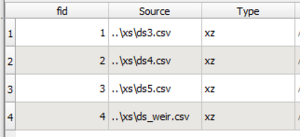
- Create a new folder entitled xs in the TUFLOW\model folder. Copy the csv files listed below from the Module_data\Module_02\Creek folder into the newly created TUFLOW\model\xs folder. These csv files in combination with the layer 1d_xs_FMT_M02_creek_001_L will be used to define the geometry and locations of the river channel cross sections.
- ds_weir.csv
- ds3.csv
- ds4.csv
- ds5.csv
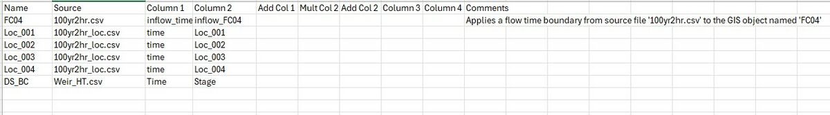
- Copy the csv file Weir_HT.csv from the Module_data\Module_02\Creek folder to the TUFLOW\bc_dbase folder. This csv file contains the stage time data that will be applied at the downstream boundary node 'DS_BC'. A constant stage value of 35.5m AOD has been applied .
- An additional row needs to be added to bc_dbase_FMT_M02.csv to apply the stage-time values from Weir_HT.csv. The revised bc_dbase should look like the figure below:
- As there is gap between the final node of the Flood Modeller network and the start of the ESTRY network a connector "X" type channel type has been added to connect them. This is present within the 1d_nwk_FMT_M02_channels_001_L layer. This must be digitised from the ESTRY channel (from the first vertex on the polyline) to the Flood Modeller node.
- To complete the "X1DQ" link a manually created ESTRY node must be snapped to the Flood Modeller node and have a "Conn_1D_2D" attribute of "X1DQ" specified. To do this, import an empty 1d_nwke_empty_P.gpkg with the name 1d_nwke_X1DQ_P into the project GeoPackage file FMT_M01_002.gpkg
- Open the layer 1d_nwke_X1DQ_P and turn on Toggle Editing. Add the attribute values shown in the table below. Save the layer.
Attribute Value ID ds2 (remember that Flood Modeller is case sensitive) Type Node Conn_1D_2D X1DQ
Conclusion
The ESTRY pipe network for the proposed development has been connected via an "X1DH" link to discharge via two pipes into the Flood Modeller network by snapping together the nodes in a 1d_nwk_L layer to a node in the 1d_x1d_P layer. A 1d_nwk_L layer has been added to represent the open channel network downstream of the Flood Modeller network in ESTRY. The cross section data for this open channel network has been defined by adding a 1d_xs_L layer with links to the source csv files at every cross section location. A connector "X" type channel is present and a 1d_nwke_P layer has been added to connect the ESTRY and Flood Modeller open channel networks via an "X1DQ" link. Please return to the main page of the Flood Modeller Tutorial 2.
Up  Back to Tutorial Module 02 Main Page

