Quadtree and Sub-Grid Sampling FAQ
Which of the TUFLOW solvers support Quadtree and Sub-Grid Sampling (SGS)?
Quadtree and Sub-Grid Sampling are currently only supported by TUFLOW HPC. The features are currently not available using TUFLOW Classic or TUFLOW FV.
How coarse can the base cell size be for a Quadtree model with Sub-Grid Sampling (SGS)?
There are two answers to this question depending on your modelling objectives. For example, by doubling your base cell size, and not changing the Quadtree levels, you will be doubling the cell sizes throughout your model. Provided this doubling of cell sizes does not conflict with other objectives (remember, only one velocity is calculated per cell face, so a consequence of doubling cell size is to reduce the quality of velocity based outputs such as hazard), whether or not it is okay to increase the base cell size simply comes down to whether results convergence can be proven. By results convergence we mean you can increase (or decrease) your cell sizes without unacceptably changing the model results. If you do see a significant change in results that is considered unacceptable, then you need to possibly make your cell sizes smaller (not larger!). A well-designed model mesh is one where you can decrease cells sizes without seeing an unacceptable change in results. SGS will greatly help with achieving results convergence and very much increase your ability to use a coarser base cell size or coarsen up parts of your model.
The second part of the answer is if you wish to coarsen up parts of your model but retain the same cell sizes in your focus area. To achieve this you can increase your base cell size to your largest cell size you wish to use, then add additional levels of nesting layers for your Quadtree mesh noting that the 2020-01 release of TUFLOW allows for up to 9 levels of nesting, so your smallest cell size can be (1/2)8, or 1/256, of your base cell size.
When should I use SGS?
Almost every time to take advantage of the higher accuracy. There is a threshold beyond which SGS isn’t required. The benefit of SGS is focused on cells with variety of elevations within each cell. For flat cells, where all SGS sample points have almost the same elevation, there won’t be much of a difference in comparison without SGS, as there is no detailed sub-cell terrain to sample.
When should I use Quadtree?
The main advantages of using Quadtree are shorter run times, lower GPU RAM footprint and smaller size of output files. Shorter run times are achieved with considerable cell count reduction compared with using a HPC grid, some models with cell count reduction of only around 30% may even run slower with Quadtree than the original HPC model.
Reasons for using Quadtree depend on modelling objectives and include:
- Large models that require higher resolution in the focus area (e.g. the town is the focus but the model due to boundaries, etc goes much further afield).
- Where high resolution velocity-based outputs (e.g. velocity, hazard, bed shear stress) are required. SGS is great for enabling the use of larger cells with good results convergence, but it still only produces one (average) velocity per cell. Quadtree will produce higher velocity output resolution (noting run times might become slower due to smaller cell sizes).
- Often popular for urban models where the streets, which take the bulk of the flow, are modelled at a higher resolution than properties, parks, etc. Where buildings and other obstructions are in an urban flowpath a higher resolution along the flowpath may be utilised.
When should I use a combination of SGS and Quadtree?
Based on the benchmarking so far there seems to be little reason not to use SGS with Quadtree. The combination of SGS and Quadtree is particularly powerful for large models that require higher resolution in the focus area as this allows much larger cells away from the focus area without affecting the results.
SGS was not made the default in the 2020-01 release because for some models, especially those with coarse cell sizes over highly variable terrain, substantially different results can be seen due to SGS picking up a lot more detail of the terrain within a 2D cell. Using Quadtree with SGS, and by using coarser cells, much better results and good results convergence can be achieved.
The resolution of my underlying DEM is 1m and my 2D cell size is 1m. Is there any benefit in using SGS?
None or very little benefit. The DEM resolution really needs to be finer than the 2D cell size resolution for SGS to be of any benefit. In this case the SGS sampling resolution would effectively be one point per cell area/face, so there wouldn't be any precision benefit and the model will have an unnecessarily longer initialisation time.
My SGS Sample Target Distance is set to 1 metre, but the model output resolution is larger than 1 metre. Why?
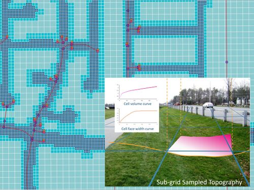
The SGS Sample Target Distance sets the spacing at which elevations are sampled within each 2D cell. It does not define the 2D cell resolution. SGS works by sampling the terrain at a finer scale within each computational cell to improve how topography is represented. The hydraulic behaviour across the cell is determined using these smaller elevation samples, without changing the actual size of the 2D cells themselves.
For example, with an 8 m cell size and a 2 m SGS Sample Target Distance, the DEM is sampled at 5 points across each cell face. This results in 5 elevation points being used to define the flow area versus elevation relationship at each 2D face, and 25 elevation points used to define the volume versus elevation relationship within the 2D cell. This allows more detail from the input topography to be captured while maintaining the original grid size.
However, TUFLOW still stores only one velocity value per face and one depth value per cell. This means the resolution of mesh based outputs (e.g. XMDF) and standard grid outputs (e.g. ASC, FLT, TIF) is not reduced to match the SGS Sample Target Distance.
When SGS is enabled, users can output high resolution water level and depth outputs based on the cell centre water level and the sampled sub-grid elevations (see: TUFLOW HR Output). However, if higher resolution velocity or velocity derived outputs (such as hazard) are required, this must be achieved by reducing the 2D cell size, not by adjusting the SGS sampling settings.
Does using SGS increase model runtimes?
Turning SGS on can increase run times by 20-30% for a model that is well designed with appropriate cell sizes. However, in cases where the model resolution is too coarse for the terrain, the improvement in model stability and hydraulic performance by using SGS can actually cause a reduction in run times. For example, for a direct rainfall model of the Johnstone River catchment SGS vastly reduced the choking of narrow flow paths caused by one elevation per cell face in the steeper part of the catchment, thereby reducing high depth and high velocity areas that allowed the simulation to progress at much larger timesteps reducing the simulation time from 26 hours to 4(!). Using SGS may allow you to use larger cell size(s) without adversely changing results so that runs can be performed much faster - this is of great benefit when developing or calibrating a model when you wish to have a high turnover of simulations - if you can carry out this phase of the modelling using coarser cell sizes by using SGS without greatly changing results your workflow efficiency can be greatly enhanced.
Should the same model using Quadtree with smaller cell count always be faster than HPC?
Not necessarily. By default, running a model with a single level Quadtree mesh identical to a HPC grid is always slower, on average 20%. Quadtree really starts to have major benefits once there is at least three levels of cell size and judicious refinement resulting in 80% of cell count reduction. There is one major benefit of Quadtree regardless in that in nearly always has a much smaller GPU RAM memory footprint because unused 2D cells within the bounding rectangle used by a HPC grid are not stored in memory whereas for a grid they are.
I'm using SGS and my water level extent is larger than depth extent. Why?
For map outputs, the default for SGS models is to treat whether a 2D cell is wet or dry differently for water level surfaces compared to other map outputs. For water level surfaces a cell is wet if any part of the cell is wet (based on the lowest elevation from the SGS sampling), therefore, all partially wet cells are flagged as wet and will appear wet in the XMDF and other map output. The advantages here are as a modeller you can see which cells are wet even if they are only partially wet, and there is no need to buffer the water level surface for high quality mapping produced by subtracting the DEM from the water level surface. For all other map outputs a cell is deemed wet only if the water level in the cell exceeds the SGS elevation at the 2D cell centre. This was necessary as otherwise greatly distorted depth, hazard and other outputs could occur by taking the depth at the lowest part of the cell based on the SGS sampling. There are a range of commands that allow you to adjust the default settings for map outputs using SGS. For example, full extend would be useful to specify for all grids that are all going to be trimmed by the DEM. For a more detailed discussion and a description of these new commands see Section 7.5.4 in the 2020-10 Release Notes.
Note there is a new remap function as a part of the asc_to_asc utility that can be used to post-process the result grids using a finer resolution DEM to produce high resolution mapping. See TUFLOW Remapping.
As of 2020-10-AB build, new high resolution output can be used to output high resolution grids directly from TUFLOW. e.g. skip post processing with the asc_to_asc utility.
Why should I create more Z Shape ridge/max lines with SGS models?
When the SGS parameters are being processed, every cell face will store its own curve of flow area versus elevation. TUFLOW doesn’t actually know the location in the cell or along the cell face where the lower elevations are, it just parametrises that they exist. As such, SGS isn't a grid within the model grid. It allows water to flow from low point to low point within the same cell even if there is higher point in between them.
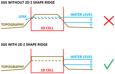
Without breaklines SGS will be more likely to allow "leaks" through a levee or embankment compared to running the model without SGS. This is because SGS sampling will pick up lower elevations either side of the levee where the 2D cell extends over both sides of the levee, and therefore produce lower flowpaths through the levee or embankment. Therefore, the need to represent all hydraulic controls such as levees (artificial or natural), road/rail embankments, etc is even more important for SGS models (this practice should be carried out for all TUFLOW models, but even more so for SGS models). In summary, it is highly recommended to add 2d_zsh ridge/max line for every levee, road/rail embankment, etc in SGS models to achieve closer results with non SGS models.
The breakline feature in asc_to_asc utility can be very useful for easily creating breaklines from a DEM.
For Z shape polygons raising elevation, if the high ground ridge of the polygon isn't aligned exactly with the cell face, there will be lower elevation values in the SGS cell face width versus depth curve which could let water to leak. To overcome this, Z shape ridge line should be used along the Z shape polygon perimeter to enforce its shape.

Why shouldn't I use Z Shape gully/min lines with SGS models?
When the SGS parameters are being processed, every cell face will store its own curve of flow area versus elevation. TUFLOW doesn’t actually know the location in the cell or along the cell face where the lower elevations are, it just parametrises that they exist. As such, SGS isn't a grid within the model grid. It allows water to flow from low point to low point within the same cell even if there is higher point in between them. It automatically defines the minimum flow paths.
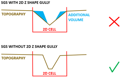
If the DEM is fine enough, SGS can preserve the gully along the cells without using any gully line. In such case using a gully line may overestimate/underestimate the width of the flow path. By default, a gully line applies a gradient along the faces based on the cell corners and cell side Zpt values, and creates sloping cells using the ZC, ZU, ZV and ZH values. The overestimating effect will get more pronounced when cell sizes are increased, e.g. wider unrealistic flow path is created when gully lines are still used in the model.
The same recommendation would also apply to the Z Shape predecessor - Z Line.
If the DEM is not fine enough, the recommendation is to create TIN with Z Shape polygons, polylines and points to create a realistic amount of volume in the model independent of cell size.

With SGS, can I have less cells across the main channel than is recommended for HPC without SGS?
You can get accurate results with less 2D cells across the width of flow if you use SGS with a high resolution DEM or preferably a TIN that is based on accurate field surveys. The quality of the channel’s bathymetry is critical to the quality of the modelling, ideally the TIN would extend to dry ground if the data are available to avoid bumpy terrain data from the DEM along the edge of the TIN within the channel (this is even more so for concrete trapezoidal channels). Benchmarking to check similar results are achieved using a finer mesh is strongly recommended to demonstrate the coarser mesh is not affecting results.
Having less 2D cells is however not recommended when using gully lines or wide Z shape gully lines, as they only modify the ZU, ZV, ZC and ZH elevations – there is no high resolution SGS sampling so the resulting modification produces a zig-zag channel perpendicular to the cell faces. For wide gully lines this zig-zag channel can be modifying different number of cell faces so the flow or conveyance of the channel can be continually constricted and expanded as a consequence. They also won’t be a good representation of the true shape of the channel. The constant change in flow area and the channel not having a smooth conveyance could also cause the flow to repeatedly transition from subcritical to supercritical causing the water level to be erratic (Froude number to be jumping around 1). When the channel runs in supercritical flow regime, it is more important to check that the model is conserving the water energy level well (include "E" into Map Output Data Types ). Flow close to a Froude number of 1 is always likely to be jumpy as so much energy is hidden in the velocity of the water, but as long as the energy line is not bumpy, the water surface profile can be regarded as a sound result.
If I run one SGS model, double the cell size and run it again, will I get the same results?
Firstly, you'll never get identical results - this will never happen with any hydraulic modelling software. However, using SGS greatly improves your results convergence when changing cell sizes, therefore you're much more likely to be able to demonstrate results consistency between the two runs if using SGS. Of importance is that your hydraulic controls are well-defined using breaklines as discussed above - ensure this is the case before running the two simulations. Note as discussed further above that there is only one velocity calculated per cell face (this is a depth and width averaged velocity) - increasing the cell size with SGS on may produce consistent water level and flow results, but you will see a smoothing of your velocity based map outputs as the velocity for the larger cell size will be based on that over a larger flow area. If there are significant velocity gradients across the channel you might need to use a finer resolution to achieve results convergence. Finally, as always, simply run both simulations and spend some time comparing your results in your focus area(s) to ensure the coarser cell size is not adversely affecting your modelling, but you should expect to see a much improved results convergence using SGS.
My HPC model runs with double precision, using SGS the model initialisation slows down significantly. Why?
As of build 2020-10-AB, the slow initial processing time for SGS and double precision has been resolved. For earlier releases this was due to an Intel compiler issue where the grid inspection has to be carried out with un-optimised code and will be slow. However, note that the HPC solution scheme (including Quadtree) doesn't generally require double precision engine. Also, if XF files are enabled (default), subsequent initialisations will be much faster.
Do I need to use "SXL" option for pits and why is my model causing "pit inlet level" error?
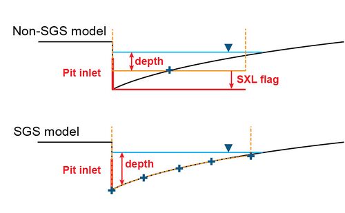
In non-SGS models, the "SXL" option is often used to lower the pit ground level to improve flow capture. However, an SGS model creates evaluation-storage relationships at cells based on the underlying DEM and is naturally better at capturing flows at pit inlets. Therefore "SXL" option is not necessary in an SGS model if the DEM is fine enough. On the other hand, users may receive "ERROR 1278 - Pit <pit ID> inlet level is below lowest channel/pipe bed." after converting a working non-SGS model to an SGS model. Since the lowest elevation sampled inside a cell is used as the “pit inlet level”, an SGS model might pick up an elevation lower than the pipe invert level. In such case, the "US_Invert" attribute of the 1d_nwk GIS layer can be used to manually specify the ground elevation of the pit.

How to decide between using SGS, Quadtree and 1D open channel?
The number of 2D cells across channel is critical. Based on the ARR 2D modelling guidelines the aim is to have 6 cells across the river, creek or drain (if not using SGS). However, use of SGS does allow use of a much fewer cells across a waterway whilst preserving the total conveyance of the waterway. The only downside of SGS is that if the velocity distribution across the waterway, or for example the super-elevation of the water surface around a bend, is important then sufficient number of cells is needed to accurately reproduce the velocity distribution or water level variation. Quadtree grid can be useful for this purpose.
How can I convert 1D open channel into Quadtree?
Follow these steps to create a TIN from ESTRY cross section inputs that can be read into a Quadtree model:
- Use the following script that has been developed to convert ESTRY cross sections inputs into 2d_zsh line and points: https://gitlab.com/tuflow-user-group/tuflow/data-pre-processing/estry_to_zsh
- Digitise a 2d_zsh merge polygon around the 2d_zsh lines and points that define the open channel. Tutorial Module 2 provides instructions on how to create this 2d_zsh merge polygon: Tutorial M02 Part2 - Other Topographic Updates
- Read the 2d_zsh line and points cross section inputs into the model using the "Read GIS Z Shape" command in the tgc file.
- Read the 2d_zsh merge polygon into the model using the "Create TIN Zpts Write TIN" command in the tgc file.
| Up |
|---|
