TUFLOW CATCH Tutorial M03 TUFLOW FV GIS Inputs QGIS
Introduction
The TUFLOW FV mesh and the TUFLOW FV materials layer (2d_mat) are supplied and inspected. The downstream culvert is redefined in TUFLOW FV format, using supplied files. Upstream and downstream boundaries are created to define the TUFLOW FV boundary.
Review Supplied TUFLOW FV Input Files
Navigate to the TUFLOW_CATCH_Module_03\Tutorial_Data folder.
- Copy Stream_Mesh.2dm and DEM.asc into the Modelling\TUFLOWFV\model\geo folder.
- Note: The DEM.asc file is a duplicate (in a different format) of the DEM.tif in the TUFLOW\model\grid folder. The .asc version is required for TUFLOW FV.
- Copy TC03_culvert_dbase_001.csv into the Modelling\TUFLOWFV\model\csv folder.
- Copy the following GIS layers into the Modelling\TUFLOWFV\model\gis folder:
- 2d_ns_TC03_culverts_001_L
- 2d_ns_TC03_weir_001_L
- 2d_mat_TC03_FV_001_R
TUFLOW FV Mesh
TUFLOW FV solves the Nonlinear Shallow Water Equations using an unstructured mesh, commonly referred to as a flexible mesh. A TUFLOW CATCH hydrology simulation requires a flexible mesh. This mesh covers the TUFLOW FV model extent, which in this case, is the receiving waters (the stream).
- Load the Stream_Mesh.2dm from the TUFLOWFV\model\geo folder into QGIS.
- In the QGIS Layers panel, right click on Stream_Mesh and select 'Properties...'. Update the symbology to view the mesh rendering:
- In 'Symbology', in the 'Contours' tab, set the 'Opacity' to 0%.
- In the 'Rendering' tab, tick on 'Native Mesh Rendering'.
- Click 'Apply', then 'OK'.
- Inspect the mesh. In particular, zoom into the low lying bank areas where eddies form. Notice that the main channel contains quad cells, while the eddies contain triangular cells.
TUFLOW FV works on a flexible mesh, made up of quadrilateral (quad) and triangular cells. Quad cells are generally used in channels as they align with the main flow direction, which allows for better numerical accuracy and computational efficiency. Triangular cells are used in inlets and complex areas to better fit irregular boundaries and to capture multi-directional or circulating flow, such as eddies.
TUFLOW FV Materials
A materials GIS file is used to define the landuse within the TUFLOW FV mesh. The material ID's in this layer are unrelated to those in the TUFLOW HPC materials layers. As such, the same material ID numbers can be used.
- Note: TUFLOW FV defines materials without a materials database. In this tutorial, the material properties will be defined in the receiving model section of the TUFLOW CATCH Control file.
- Load the 2d_mat_TC03_FV_001.shp from the TUFLOWFV\model\gis folder into QGIS.
- Click on the 'Apply TUFLOW Styles to Open Layers' symbol from the TUFLOW Plugin toolbar.
- Inspect the materials layer.
Downstream Culvert Update
In the previous section (TUFLOW HPC GIS Inputs), the downstream culvert was removed as it was located within the TUFLOW FV mesh. As such, it needs to be redefined in TUFLOW FV format.
- Load the 2d_ns_TC03_culverts_001_L.shp and 2d_ns_TC03_weir_001_L.shp from the TUFLOWFV\model\gis folder into QGIS.
- Click on the 'Apply TUFLOW Styles to Open Layers' symbol from the TUFLOW Plugin toolbar.
- Inspect the supplied files. To define the culvert, two nodestrings are needed, one on the upstream end and another on the downstream. The weir enforces the road crest, while allowing water to spill over. Notice that the nodestrings have been placed within a row of the mesh.
- In TUFLOW FV, 1D culvert attributes are defined in a separate .csv database. Navigate to the TUFLOWFV\model\csv folder and open TC03_culvert_dbase_001.csv.


Create TUFLOW FV Boundaries
TUFLOW FV uses nodestrings (2d_ns) to specify the location of open boundary conditions. Create the 2d_ns layer using the TUFLOW CATCH plugin:
- Go to Processing > Toolbox from the top dropdown menu options to open the Processing Toolbox.
- Go to TUFLOW Catch in the processing tool list and select 'Import Empty'. This opens the dialog shown below:
- Project Directory: This should automatically be set to the TUFLOW_CATCH_Module_03\Modelling folder
- Empty Type: Click '...', and tick on '2d_ns' from the empty type list.
- Geometry Type: Click '...', and tick on 'Line'.
- Run ID: TC03_US_boundary_001
- Click 'Run'.
- Once the tool has finished, click back to the 'Parameters' tab. Update the 'Run ID' to TC03_DS_boundary_001.
- Click 'Run'. Once the tool has finished, click 'Close'. The 2d_ns_TC03_US_boundary_001_L and 2d_ns_TC03_DS_boundary_001_L will appear in the QGIS Layers panel.
- In the QGIS Layers panel, select (left click) 2d_ns_TC03_US_boundary_001_L and toggle on editing.
- Select 'Add Line Feature'.
- Zoom in to the upstream end of the mesh and digitise a nodestring just outside the mesh boundary. Ensure the nodestring overhangs the mesh edges and is digitised from the right bank to the left bank when looking downstream. Use the right mouse button to terminate the line, and an attributes dialog will appear. Set the ID to 'US' and click 'OK'.
- Turn off editing to save the edits.
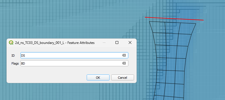
- Repeat this process for the downstream boundary 2d_ns_TC03_DS_boundary_001_L, at the downstream end of the mesh. For this nodestring, set the ID to 'DS' and the Flags to 'BD'. The BD flag will snap the nodestring along the outer edge of the mesh.
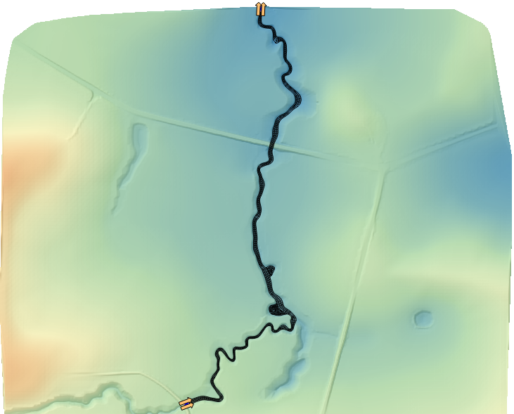
- Use the 'Apply TUFLOW Styles to Open Layers' to check that the orientation of the nodestrings. The arrows should point in the direction of flow (downstream).


| Up |
|---|