Tute M01 Boundaries QGIS Archive
Introduction
This page details the method for using QGIS to create the GIS based boundary layer files. Once the GIS layers are setup (detailed in this page), these are linked to data using a boundary database, (the boundary database is described in Module 1). We will create three different boundaries:
- Upstream flow boundary
- Downstream water level - flow (stage-discharge) boundary
- Internal flow boundary
The first two boundaries are input into a 2d_bc type layer. The third boundary (internal flow boundary) will be applied as a source-area boundary in a 2d_SA boundary type layer.
Method
2d_bc Type Boundaries
We will create the 2d_bc boundaries first. These boundaries are external and will "snap" to the edge of our active model area. Both of these boundaries have been aligned perpendicular to flow direction.
Note: This line orientation is recommended for 2d_bc QT, HQ and HT boundary inputs. Care should be taken to digitise these boundary types perpendicular to flow direction (i.e. across the waterway). If they are digitised oblique to the flow (i.e. not perpendicular) model instabilities can result in some cases.
- Load the DEM Module_Data\DEMs\QGIS\DEM_M01.img
- Load the code polygon TUFLOW\model\gis\2d_code_M01_002_R.shp (this was created in the previous step).
- Load the template 2d bc type layer (2d_bc_empty_L.shp) from TUFLOW\model\gis\empty\.
- Save a copy of the template under the TUFLOW\model\gis folder as 2d_bc_M01_002_L.shp. Note that we save the file into the \model\gis\ directory not the \model\gis\empty\ directory.
- Open the newly saved, 2d_bc_M01_002_L.shp add it to the map window and close the template. The QGIS window should now look something like this:
- The first step is to change the style of the code region to make it a bit easier to work with. Right click on the 2d_code_M01_002_R in the layers section and select properties.
- In the Style tab, select the "Change" button, highlighted with a red oval in the image below.
- In the Symbol Layers section, select the Add Symbol Layer.
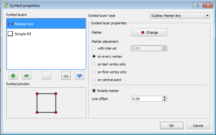
This gives us to symbol layers for the same file. For the first layer set the following options (see the 1st image below):- Set the Symbol Layer Type to Outline: Marker Line
- Set the Marker placement to On Every Vertex.
For the second Symbol Layer set the following options (see the 2nd image below):- Set the Symbol Layer Type to Simple Fill
- Set the Fill Style to No Brush.
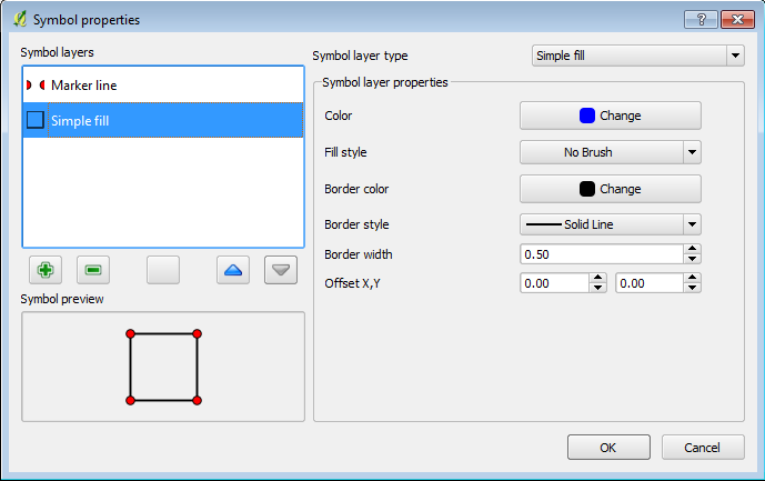
The first layer sets the vertices (nodes) along the polygon line as visible, the second makes the polygon display as an outline only. This is important as we need to snap the boundary lines to the vertices on the code polygon. After applying the style changes the QGIS window should look like the image below.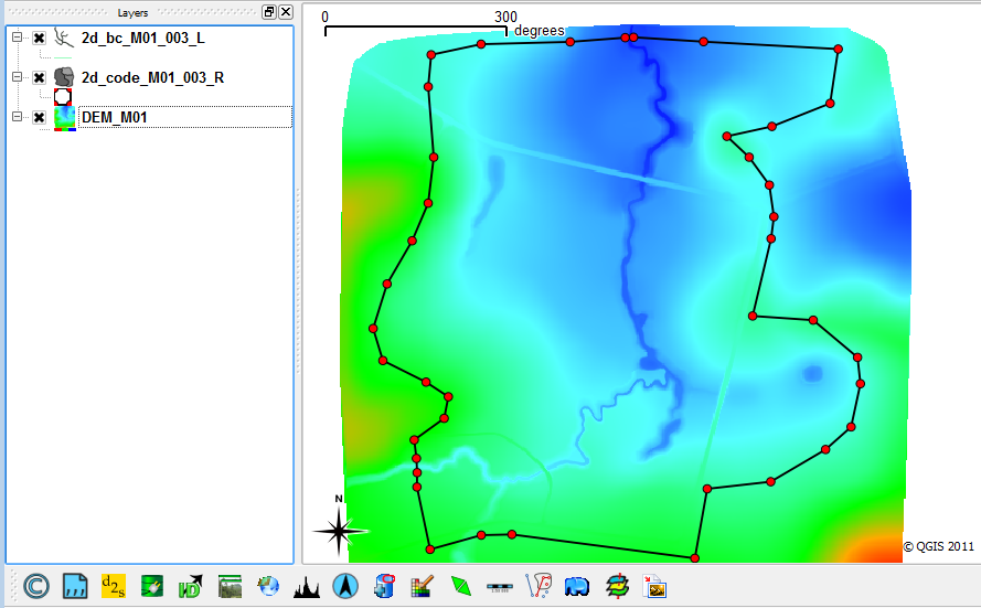
- Before we begin modifying the 2d_bc layer, we need to enable snapping to the 2d_code region. To enable snapping select the Settings >>> Snapping Options...
Select the check-box next to the 2d_code_M01_002_R item. Set the tolerance to 5 map units (5 metres) and select apply. - Zoom into the creek at the south-western edge of the code polygon. Toggle editing for the 2d_bc_M01_002_L layer and then select the Capture Line. Create a line joining the four vertices shown below, when selecting the final vertex, use the right mouse button to terminate the line. When drawing the line, the cursor should snap to the existing vertices on the 2d_code layer.
- When you terminate the line, an attributes dialog will be displayed. Enter the following data:
- Type = QT
- Flags = Blank (remove the null)
- Name = FC01 (that is FC Zero One)
NOTE In QGIS, at this stage it is necessary to enter 0 in the f, d, td, a and b attributes. Most GIS store null numeric field entries as zero, QGIS does not it stores a null entry, however TUFLOW requires these to be entered, for later releases of TUFLOW this will be changed to recognise the QGIS null entry.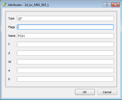
- At the downstream boundary (north of the code polygon), add another shape connecting the four vertices shown below.
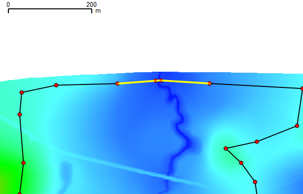
In the attributes window set the following:
- Type = HQ
- b = 0.01
NOTE In QGIS, at this stage it is necessary to enter 0 in the f, d, td and a attributes. Most GIS store null numeric field entries as zero, QGIS does not it stores a null entry, however TUFLOW requires these to be entered, for later releases of TUFLOW this will be changed to recognise the QGIS null entry.
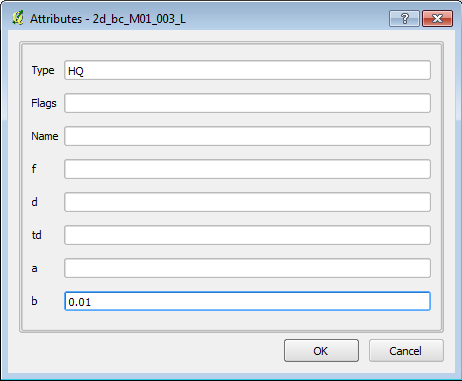
The type "HQ" designates this as a Water Level ("H") versus Flow ("Q") boundary. This is a stage-discharge boundary condition. If a Name is specified, the user must define this stage-discharge relationship in the boundary database. In this case a water surface slope value is specified via the "b" attribute, this value of 0.01 is in metres per metre and corresponds to a 1% water surface slope. TUFLOW will automatically create a stage-discharge curve flow this location, based on the underlying topography, roughness and specified water surface slope.
The remaining attributes are to be left blank or with the default value of 0 (including the name). - Toggle the editing off and when prompted save the 2d_bc_M01_002_L.


2d_sa Type Boundary
The next step is to create an internal inflow boundary using a source-area inflow this is done with a 2d_sa type layer.
- Load the 2d_sa_empty_R.shp template file from the TUFLOW\model\gis\empty\. Save a copy of the layer in the TUFLOW\model\gis\ directory as 2d_sa_M01_002_R.shp.
- Load the newly created 2d_sa_M01_002_R file and close the template file.
- Add the layer to a map window with the DEM.
- Add a new shape and digitise a polygon around the dam in the lower right (south-east) of the screen.
- When prompted enter "FC04" under the Name attribute (FC zero four, without the quotes).
- Finish the edit by toggle the editing and when prompted, save the file.


Conclusion
QGIS has been used to create the 2d_bc layer that contains an upstream "QT" type inflow boundary and a downstream "HQ" stage-discharge type boundary. A second QGIS layer (2d_sa) defines an internal source boundary. Our next step is to assign hydrographs to the boundary locations created in this page. Please return to the tutorial model page here.