Tute M01 Model Controls SMS Archive
TUFLOW Simulation
A TUFLOW simulation is comprised of a grid, feature coverages, and model parameters. We have created a grid and several coverages to use in TUFLOW simulations. SMS allows for the creation of multiple simulations each of which includes “links” to these items. A link is like a shortcut in windows. The data is not duplicated; rather, the link points to where to go to get the data. The use of links allows these items to be shared between multiple simulations. A simulation also stores the model parameters used by TUFLOW.
We created the TUFLOW simulation catalogue previously when we were assigning the default active/inactive status and default materials definition. To refresh your recollection, we created the catalogue by:
- Right clicking an empty part of the project explorer and choosing New Simulation | TUFLOW. This created several new folders that we will discuss as we go. Under the tree item named Simulations, there was a new tree item named “Sim.”
- We rename the simulation tree item to “M01_5m_002.”
Geometry Components
Rather than being included directly in a simulation, grids are added to a “Geometry Component” which is added to a simulation. The geometry component includes a grid and all coverages which apply directly to the grid. Coverages that should be included in the geometry component include: 2D BC coverages (if they include code polygons), geometry modification coverages, 2D spatial attribute coverages, and area property coverages.
We created the geometry component previously when we were assigning the default active/inactive status. To refresh your recollection, to create and set up the geometry component:
- We right clicked on the folder named Components and choose New 2D Geometry Component.
- We rename the new tree item from 2D Geom Component to 5m geo.
- We dragged the grid ("5m") item under this tree item.
- Now we need to add other coverages under the geometry component tree. Drag the "Materials" and “BC” coverages under tree.
Material Sets
Now that we have a Simulation, we need to define our material properties. There is already a Material Sets folder but we need to create material definition sets or a set of values for the materials. To define material properties:
- Right click on the Material Sets folder and select New Material Set. A material set will appear below the Material Sets folder.
- Right click on the new material set in the project explorer and select Properties. The materials are displayed in the list box on the left.
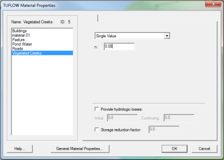
- Click on each material name and change the values for Manning's n for the materials according to the table below. Click OK when done.
| Material | Manning's n |
|---|---|
| Pasture | 0.06 |
| Roads | 0.022 |
| Buildings | 3 |
| Ponds/Water | 0.03 |
| Vegetated Creek | 0.08 |
Simulation Setup and model parameters
The simulation must include a link to the geometry component and to each coverage used that is not part of the geometry component. In our case, all of the coverages in our simulation are part of the geometry component.
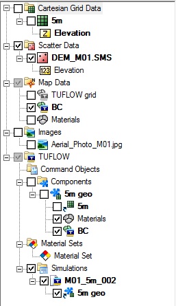
To create the link to the geometry component, drag the geometry component "5m geo" onto the simulation in the project explorer. Compare your project explorer with the image to the below.

The TUFLOW model parameters include timing controls, output controls, and various model parameters are set using the 2D Model Control. To set up the model control parameters:
- Right click on the M01_5m_002 simulation and select 2D Model Control.
- Click on Time option from the list to switch to the Time tab if it is not already selected. Set the Start Time to “0” hours and the End Time to “3” hours. Change the Timestep to “1.5” seconds. The rule of thumb is that the timestep should be about half the cell size in seconds.
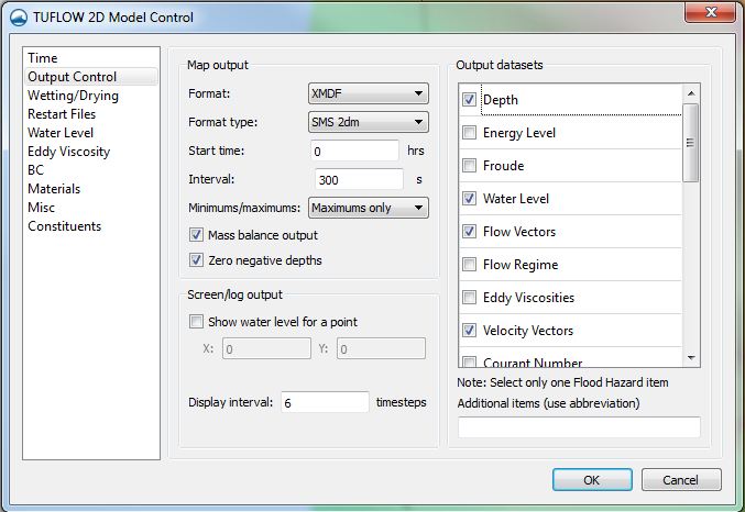
- Click on the Output Control option from the list to switch to Output Control tab. Set the following:
- In the Map Output section, set the Format Type to "SMS 2dm"; the Start Time to “0” hours and the Interval to “300” seconds (5 minutes).
- Set Minimums/Maximums to “Maximums Only.”
- In the Output datasets section, select the following datasets: Depth, Water Level, Flow Vectors, Velocity Vectors, and Mass Error %.
- In the Screen/Log Output section, change the Display interval to "6". While TUFLOW is running, it will write status information every 6th time steps.
- Click on Water Level option in the list to switch to the Water Level tab and change the Initial Water Level to “0.0”. Make sure that the Override Default Instability Level option is not selected.
- Switch to the BC tab and using the drop down list switch the BC Event Name to "100 year".
- Click OK to close the Model Control dialog.

Saving a Project File
To save all this data for use in a later session:
- Select File | Save New Project.
- Save the file as “2dflow.sms”.
- Click the Save button to save the files.
See Run TUFLOW from within SMS for instructions on how to run TUFLOW from within SMS.
