Tute M02 Arc 1d2d Link Archive
- Using a point object in the 2d_bc type layer;
- Using a line object in the 2d_bc type layer; and
- Using a point object in a 1d_nwk layer.
- Open ArcMap and ensure that the DEM (in the Module_Data) and the 1d_nwk_M02_culverts_001_L.shp are loaded.
- Open the 2d_bc_empty_P.shp file from the TUFLOW\model\gis\empty\ folder. Export a copy of this in the TUFLOW\model\gis\ as 2d_bc_M02_culv_001_P.shp. Close the template file down and open the newly created 2d_bc_M02_culv_001_P file.
- Zoom into the culvert at the south-eastern corner of the model. This culvert has the ID "FC04.1_C".
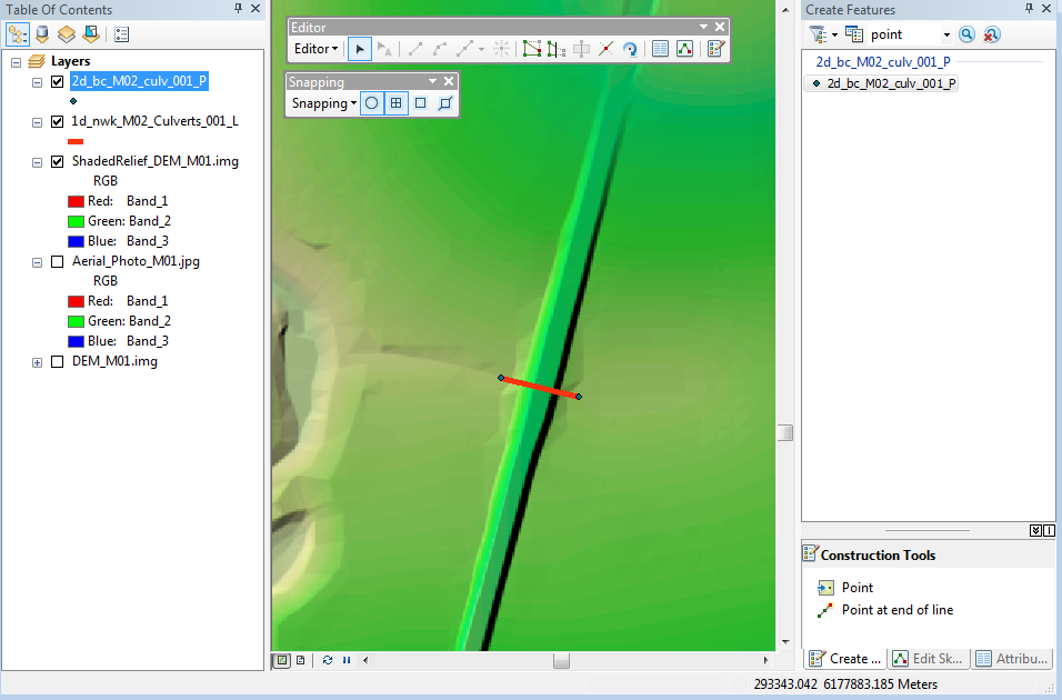
- Make the 2d_bc_M02_culv_001_P layer editable, under the editor dialog make the Snapping Toolbar visible, select the point and end snapping.
- Create a new point feature at the upstream and downstream ends of the culvert as per the image below.
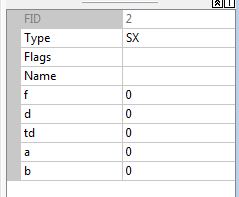
- For both objects, set the "Type" attribute to SX, the remaining attributes can be left unchanged, as per the image below.
- Finalise the edit, by toggling the editing to off and when prompted save the file.
- Open the 2d_bc line object template (2d_bc_empty_L.shp) and export a copy into the TUFLOW\model\gis\ as 2d_bc_M02_culv_001_L.shp. Close the template file and when prompted open the newly created 2d_bc_M02_culv_001_L.shp file.
- Zoom into the northern culvert location (culvert ID "FC01.2_R")
- The reason for using a line object rather than a point object is to allow the culvert to connect to more than one 2D cell. This is important where the dimensions of the 1D channel or culvert are greater than the 2D cell size. For this box culvert there are 5 cells each with a width of 2.4 metres. This could cause stability when connected to a single 2D cell.
In order to see where the 2D cells, we will open a check file created when the model was run during module 1. In ArcMap open the grid check file "M01_5m_002_grd_check_R.shp" from file can be open from the TUFLOW\check\2d\ directory.
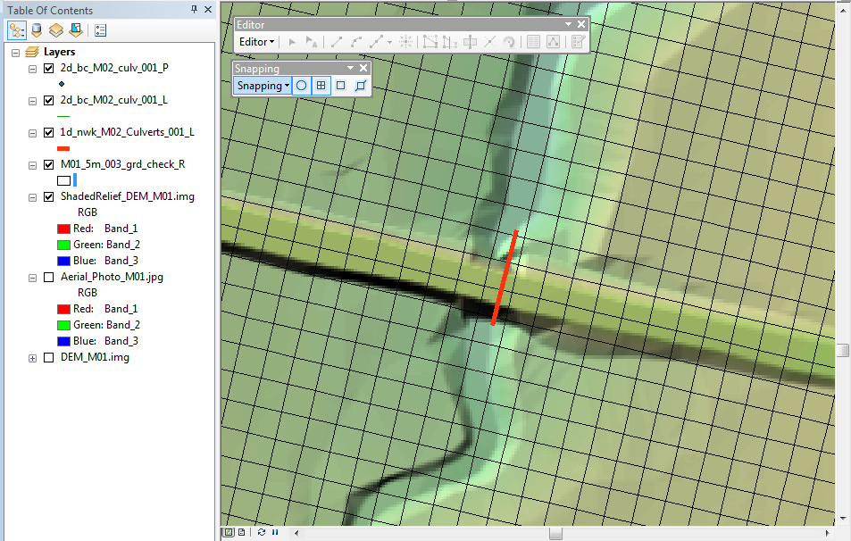
It may be necessary to change the style of the grid check file so that the layers underneath can be seen. To do this right click on the layer and select properties, change the style so that "no brush" is used in the fill style. The map window should look like the image below:
- Make the 2d bc lines layer editable and ensure the snapping tool is still activated.
- Draw a line in the location shown below and enter "SX" into the "Type" attribute This will create an "SX" type connection which selects three cells.
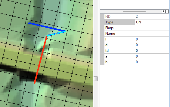
- With the snapping enabled, digitise a line connecting the culvert and the SX line. Enter "CN" in the "Type" attribute. This "CN" type line tells TUFLOW that there is a connection (CN) between the two layers.
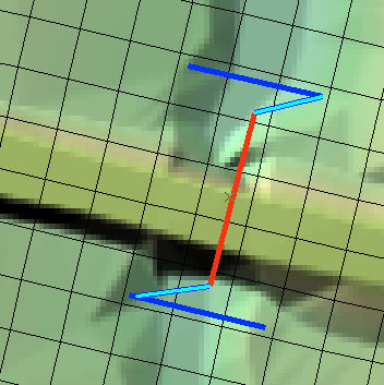
- Repeat the process for the upstream of the culvert. The final configuration is shown in the image below, the dark blue lines are the "SX" type lines and the light blue lines are the "CN" type lines.
- Toggle the editing off, and save the changes to the layer.
- Open the 1d_nwk_empty_P.shp (the _P designates that this file contains points), export a copy of the file into the TUFLOW\model\gis\ as 1d_nwk_M02_culverts_001_P.shp. When prompted open the newly created layer. Close the template file.
- Zoom into the culvert at the south-western part of the model (ID = "FC01.1_R")
- Toggle editing on the 1d_nwk_M02_culverts_001_P layer and create a feature (point) object at the upstream of the culvert. Enter the attributes as per the image below.
- Repeat the process for the downstream of the culvert.
- Finish editing the layer and save the changes.
- 2d_bc_M02_culv_001_P.shp
- 2d_bc_M02_culv_001_L.shp
- 1d_nwk_M02_culverts_001_P.shp
Introduction
This page describes the process of using ArcMap to create links between the 1D culverts and the 2D model. Three methods are described, this is done to demonstrate the available methods. Generally one of the described methods would be used.
The methods described are:
Method
The 2d_bc methods are described first.
2d_bc Link as Point Object
2d_bc Link as Line Object
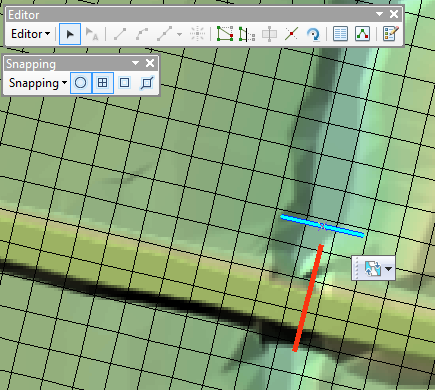
The "SX" line digitised in the step above, does not snap to the end of the culvert, to link the SX connection and the culvert we need to digitise another line from the end of the culvert to one end of the SX line.
1d_nwk link
It is also possible to create the 1D/2D links using the 1d_nwk layer. This is done by creating a node in the 1d_nwk type layer. As the shapefile format does not support lines and points in the same layer, it is necessary to create a new 1d_nwk layer.
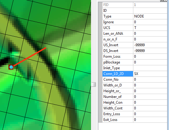
The -99,999 values entered into the US and DS_invert attributes, tells TUFLOW to find the data elsewhere, this data was entered into the culvert layer (1d_nwk). The "SX" in the "Conn_1D_2D" attribute is creating the 1D/2D connection.
Conclusion
In order to demonstrate three methods for linking the 1D elements to the 2D model we have created three new files:
The next step is to update the TUFLOW control files and run the model! Return to the module 2 page.