Tute M02 SMS 1d nwk Archive
Jump to navigation
Jump to search
Introduction
This module will use the same TUFLOW model from Module01 but, we will add culverts at the crossings. If the SMS window you are working on already has the project for Module01 loaded, then proceed to the steps, if not go ahead and load the SMS project for Module01.

Culvert Locations
The locations for the culverts that we are planning to add are provided in a MapInfo *.mif file. To setup the coverage for the culverts and read in this data follow these steps:
- Right Click on the Map Data in the Project Explorer and click on New Coverage.
- Under Models, select TUFLOW | 1D Networks.
- Name the new coverage “Culverts”.
- Click OK to exit.
- Make sure that the coverage Culverts is selected and select File | Open. Read in the file \Module_Data\Module_02\Culverts.MIF. Click OK to read the data as a GIS Layer.
- Select the "Culverts.MIF" file under GIS Data in the Project Explorer.
- Click on Mapping | Shapes -> Feature Objects. Click Yes to select all objects.
- Make sure that User existing Coverage option is selected. Click on Culverts coverage in the list and Click Next. Then click Next twice (no mapping required) and then Finish to exit Mapping dialog.
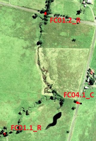
- Select Culverts coverage under Map Data in the Project Explorer. You should have now seen three little arcs added to the map (See image to the right). You may now delete "Culverts.mif" from the project explorer.
Culvert Attributes

Now that we have identified the locations of culverts, we need to specify the attributes such as the culvert sizes.
- Turn off all items in the Project Explorer except the Scatter Data and the “Culverts” coverage. Make sure that "Culverts" coverage is active
- Click on the Select Feature Arc Tool and select the FC01.1_R culvert (See figure to the right).
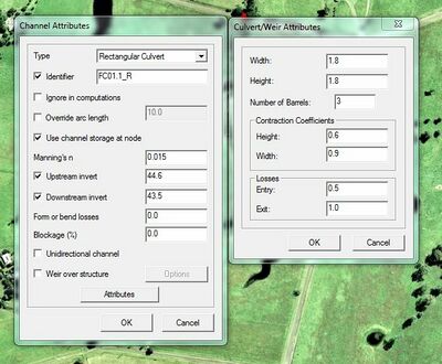
- Right click on culvert arc and select Attributes from the menu that appears.
- Change the Type to "Rectangular Culvert".
- Rather than use the default generated identifier, change the Identifier to “FC01.1_R.” TUFLOW will use this identifier when generating 1D results.
- Toggle on Use Channel Storage at Node and make sure that Ignore at Computations is not selected.
- Toggle off Override Arc Length.
- Change Manning’s n to 0.015.
- Toggle on Upstream and Downstream inverts. Enter Upstream Invert as 44.6 and Downstream as 44.5.
- Leave Form or Bend Losses and Blockage % at 0.
- Click on the "Attributes" Button to bring up the culvert attributes dialog.
- Change the Width of the culvert to "1.8", the Height to "1.8" and the Number of barrels to "3".
- Under Contraction Coefficients, change the Height to "0.6" and the Width to "0.9".
- The Entry loss should be changed to "0.5" and the Exit loss to "1.0".
- Select OK twice to exit the Culvert/Weir Attributes dialog.
- We have now added three culverts and defined their attributes. Save your SMS project with a different name and move on to another section titled "Define 1D/2D Linkages"
Using the same procedure, setup the culvert attributes for the remaining two arcs using the data in the following table. Make sure to toggle off Override Arc Length for each arc
| Culvert | FC01.1_R | FC04.1_C | FC01.2_R |
|---|---|---|---|
| Type | Rectangular | Circular | Rectangular |
| Ignore in Computations | Not Selected | Not Selected | Not Selected |
| Use Channel Storage at Node | Selected | Selected | Selected |
| Manning's n | 0.015 | 0.015 | 0.015 |
| Upstream Invert | 44.6 | 43.35 | 37.8 |
| Downstream Invert | 44.5 | 32.75 | 37.5 |
| Form or Bend Losses | 0 | 0 | 0 |
| Blockage (%) | 0 | 0 | 0 |
| Attributes | |||
| Width | 1.8 | -- | 2.4 |
| Height | 1.8 | -- | 1.2 |
| Diameter | -- | 1.2 | -- |
| Number of Barrels | 3 | 3 | 5 |
| Contraction Coefficient - Height | 0.6 | -- | 0.6 |
| Contraction Coefficient - Width / Diameter | 0.9 | 0.9 | 0.9 |
| Entry Losses | 0.5 | 0.5 | 0.5 |
| Exit Losses | 1 | 1 | 1 |