Tute M03 SMS 2d zsh Archive
- In SMS select File | Open from the menu.
- Navigate to the folder Module_Data/Module03/ .
- Select Creek_Centre_Line.xyz and select Open.
- The next dialog is titled, File Import Wizard - Step 1 of 2. Specify Comma as one of the column delimiters (it's okay if others are selected as well), make sure Start import at row is set to 1 and Heading row is selected. Click Next.
- In the next window (File Import Wizard - Step 2 of 2) change the SMS data type to "Feature Points". Make sure the Type and Header are the same in the "File Preview".
- Click Finish.
- The file should have opened and show point objects along the creek. If it is not already open, open the DEM (\Module_Data\DEMs\DEM_M01.SMS.tin) to ensure that the points are being displayed at the right locations. The points should appear as per the image below, with the points having X, Y and Z attributes. The next step is to change the data to a format usable by TUFLOW.
- In the project explorer, right click on the "Creek_Centre_Line" coverage and select Type | Models | TUFLOW | 2D Z Lines (advanced). This specifies that the data in this coverage will be read by TUFLOW as Z Lines.
- We need make sure the projection (coordinate reference system) is set correctly. To do this, Select Edit | Projection from the menu.
- In the Current Projection dialogue make sure the projection is set as UTM, WGS84, Meters, ZONE = -60.0. Set the Vertical units to Meters. Click OK once done. This is the projection of the TUFLOW model that we set in Module 1.
- Z
- dZ
- Shape_Width_or_dMax
- Shape_Options
- Using the Create Feature Arc tool, create arcs from upstream to downstream, connecting all the feature points in the Creek_Centre_Line coverage (arcs should "snap" to the points). Terminate the line of arcs and restart it again upstream and downstream of the road embankments. If you make a mistake, select the arc, delete it, and create it again (or press the escape key if you have not terminated the arc yet).
- Using the Select Feature Point tool, right click somewhere on the main window and select Select All.
- Right click on the main screen and select Attributes.
- Select Modify Z Values, change the Thickness to Thin and change the Option to Min. The "Min" in the shape options lowers the elevations only if the elevation from the breakline is below the the existing elevations in the Zpts.
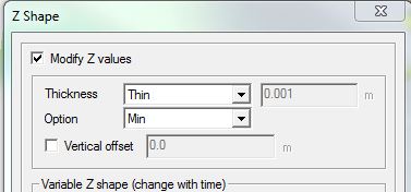
- Click OK. SMS might prompt you to confirm that you are changing attributes of these arcs. Click OK.
- Repeat the process described above:
- Import the Road_Crest_Survey.xyz file as Feature Points data with comma delimiters
- Change the Road_Crest_Survey coverage type to Models | TUFLOW | 2D Z Lines (advanced)
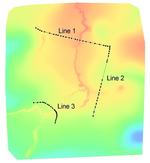
- Digitise lines along each road by connecting all nodes with feature arcs as per the image below.
- Select all of the lines, open the attributes dialog by right clicking somewhere on the main window and select Modify Z values option and set the following attributes(as described previously):
GIS Attribute Line 1 Line 2 Line 3 Thickness Thick Thin Thin Option Max Max Max - Shape_Width_or_dMax = 0 - a "thin" breakline is used, only elevations on the cell side are modified (no change in storage);
- Shape_Width_or_dMax less than or equal to 1.5 times the cell size - a line of whole cells are modified (a "thick" breakline); or
- Shape_Width_or_dMax greater the 1.5 times the cell size - a "wide" breakline, elevations in multiple cells are modified. Any Zpts within a distance of half the Shape_Width_or_dMax are modified.
Introduction
In this page, we import data from text files into SMS. Once the data is in SMS, we will set it up in the TUFLOW 2d Z Shape (2d_zsh) format ready for input into TUFLOW.
We will use the model that was created in Module 2. Go ahead and load \CompleteM_Model\Module02\Module02.sms.
Save this project as \Module03.sms so that the original file remains unchanged.
Method
Two separate sets of data have been provided in the "\Module_Data\Module03\" folder. These are simple text files with the .xyz extension; as the name suggests, these contain coordinates in a x, y and z format. In this case they are comma separated. A similar process could be used for space or tab delimited data.
Importing Text Data
The first step is to import this data into SMS. To do this:


2d Z Shape Format

The 2d Z Shape (2d_zsh) format requires the input data to be in the format outlined in the TUFLOW Manual. The first four columns of the table should contain the following attributes:
SMS provides an interface for specifying these attributes and then passes the data to TUFLOW in the correct format. First, however, we need to modify the geometry by digitizing feature arcs that can be used to define Z Line attributes. To do this:


We've just specified that the arcs we've created will form a continuous flow-path by lowering cell centres and cell sides. We will examine the changes made to the model in the check file section later in this tutorial module.
The breakline to represent the creek centre line is now ready for input into TUFLOW.
If you look at the model closely, you can see that the overland flow should be obstructed by the roadway but it has not been represented in the model allowing water to flow over the roadway. We will use Z-lines again to raise the grid cell elevation which will represent the roadway. For this, we need to import the roadway centerline.

While defining such Z-lines, we need to define line or node elevations. In this tutorial, the elevations for the points were imported in the text file. These elevations are associated with the points and no value needs to be specified on the line.
As explained in the TUFLOW Manual, for a line object the Shape_Width_or_dMax controls the width of the breakline in metres. Depending on the cell size the following methods of application are used:
In SMS the Thickness attribute automatically sets "thin" or "thick" breaklines. It also allows for specification of a width for "wide" breaklines.
Later in the module we will look at the check files to review which Zpts are modified.
Save your SMS project as \Module03.sms.
Conclusion
Two datasets have been imported into SMS and manipulated into a TUFLOW Z Shape format (2d_zsh). The next step is to modify the control files.