Tute M04 Arc 1d bc Archive
Jump to navigation
Jump to search
Introduction
In this section we will create the 1D boundary conditions layer using a TUFLOW 1d_bc file. It is in this layer that we will specify the 1D boundary conditions.
Method
- Create a copy of the 1d_bc_empty_P.shp template file from the TUFLOW\model\gis\empty folder. Save this in the TUFLOW\model\gis\ folder as 1d_bc_M04_001_P.shp.
- Open this layer and make it editable.
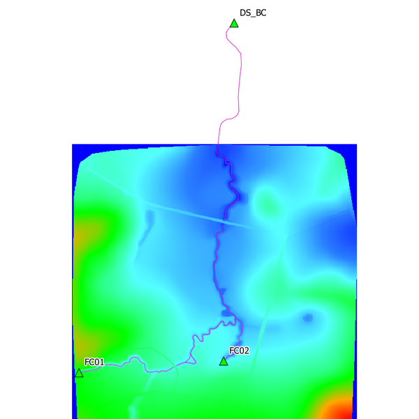
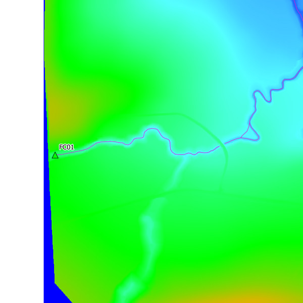
- We are going to snap three point features to the 1d_nwk_M04_channels_001_P layer, providing the necessary upstream and downstream boundaries to the creek channel. With snapping enabled in ArcMap, use the create feature tool to digitise a point feature snapped to the upstream extent of the 1d_nwk_M04_channels_001_P layer (the south western area of the model area).
- In the attributes window that is displayed, enter the point Type as QT and the Name as FC01. Make all other attributes blank by removing any null entries. The name FC01 links the boundary condition specified in the bc_database to this location in the model.
- Repeat this process and digitise a point feature snapped to the upstream extent of the secondary channel FC02. Again specify the boundary Type as QT and this time the Name as FC02. This name will link channel FC02 to the unique inflow boundary in the bc_database.
- To complete the process we need to specify the boundary condition to be connected to the downstream extent of the model located to the north. Digitise a point feature snapped to the downstream extent of the 1D channel at ds_weir. The downstream boundary is an water level versus flow boundary that assigns a water level at the downstream boundary according to the flow entering the node. Specify the Type as HQ and the Name as DS_BC.

- Stop editing the layer and save the edits to finish.

Conclusion
The 1d_bc layer is now ready for input into TUFLOW. Please return to the Module 4 main page here where the next step is to create modified TUFLOW simulation control files prior to running the model.