Tute M04 ExtractXS SMS Archive
As discussed in the main page, this workshop will be based on Module02 model which has a 5m grid and three 1D culverts. We will load this model and make necessary changes to add a 1D channel network that interacts with the surrounding 2D grid.
Loading Base Model
- Open SMS and select Display | Projection. Change the horizontal projection to UTM, Zone -60, WGS84 and meters. Similarly set the vertical projection to Local, meters. This was the projection used in Module02 TUFLOW model.
- Select File | Open in SMS. Browse and open the SMS project we created in Module02 from \Module_Data\Module04\BaseModel\Module02.sms.
- This model has the following components already defined (Refer to Module02 for further details about this model):
- 5m grid
- TIN data
- Boundary Condition polygon as BC coverage
- Materials coverage
- Location of 1D culverts as Culverts coverage
- Connection of the culverts to 2D grid as Culvert_BC and Culvert_Connections coverages. We will modify these coverages later
- A geometric component 5m geo Culvert. We will add/remove items on this component

Reading Cross Section Arcs
- In SMS, select File | Open. Browse and open the shapefile \Module_Data\Module04\XS\1d_xs_M04_creek_001_L.shp.
- This will add a new layer in the project explorer as well as add several arcs on the display. These are the locations and extents of the cross section arcs and we will need to map these arcs into the SMS data format.
- In the project explorer, right click on the "Map Data" folder and select New Coverage. Change the coverage type to TUFLOW | 1D Cross Sections and Coverage Name to Cross_Sections. Click OK to create a new coverage.
- Click Cancel to close CsDb Management dialog (we have not created a cross database yet)
- Click on Cross_Sections coverage to make it active and then click on 1d_xs_M04_creek_001_L.shp under "GIS Data" folder.
- Select Mapping | Shapes -> Feature Objects. Click Yes to use all shapes.
- In GIS to Feature Objects Wizard dialog, make sure use an existing coverage is toggled on, click on Cross_Sections coverage and click Next. Click Next and Click Finish (No need to map any attribute).
- The arcs from the shapefile have been copied into SMS coverage and we no longer need this shapefile. You can delete it from the display (Right click | Delete).

Extracting and Viewing Cross Sections
The cross sections are handled a little differently in SMS as compared to the other GIS tools mentioned in the 1D Cross-Sections of this tutorial. SMS can extract elevations from underlying DEM/TIN triangles using cross-section arcs which are then stored into a cross section database file. The SMS project we are working on already has TIN data (named DEM_M01.SMS in the project explorer) and we imported the locations and extents of the cross sections from the shapefile in the previous step. In this step we will extract elevations and material properties along these cross section arcs.
- Click on Cross_Sections coverage to make it active. Pick the Select Feature Point tool
 and highlight all of the features in the Cross Section coverage.
- From the menu select Feature Objects | Vertices <-> Nodes. This will convert all selected nodes to vertices and reduce the total number of arcs to three on each cross section(ending and beginning at the road embankments).
- In the project explorer, right click on the Cross_Sections coverage and select Extract from Scatter. This process will take few seconds to extract the elevation data.
SMS will display a warning message saying that some of the elevations for the cross sections were extrapolated. This is because we have few cross sections that are outside the extent of the scatter data. We will deal with those little later.
Click OK. - Right click on the Cross_Sections coverage one more time and select Map Materials from Area Coverage to map Manning's roughness values in each cross section. These values will be used while simulating flow through 1D channel network.
- Select Coverage dialog will appear asking you to select a coverage from which the material properties shall be mapped. Click on Materials coverage, change Default Material to be Vegetated Creek and click OK.
- Still in the Cross_Sections coverage, pick Select Feature Arc tool and double click on any of the cross section arcs. Then click on Edit button.
- This will bring a Cross Section Attributes dialog. You should see a cross section displayed for the arc you just selected. This dialog displays the X,Y and Z values along the arc as well as the types of material in the cross section.
- In Cross Section Attributes dialog, click on Line Props tab to view materials.
- Click Cancel twice when done.


Manually Entering Cross Sections
Turn on the display of scatter data from the project explorer. Then Pan and Zoom in to the northern end of the model. You should be able to see that there are six (6) cross sections outside the extent of the scatter data. Since these cross sections are outside the scatter data extents, when you extracted cross section few steps earlier, these six arcs were not assigned any elevation.

In this step we will define these cross sections manually. It is common to get surveyed sections of the channel as the LAS/LiDAR dataset are generally unable to penetrate the water surface.
The cross sections are stored as .csv files.
- Click on Cross_Sections coverage to make it active. Pick Select Feature Arc tool and double click on the cross section arc ds1 (see above image).
- Click on Edit button which will open Cross Section Attributes dialog.
- Outside of SMS, browse and open file \Module_Data\Module_04\xs\ds1.csv in a text editor or a spreadsheet program.
- Copy all the data from both columns (X and Z).
- Back in SMS Cross Section Attributes dialog:
- Make sure Geom Edit tab is selected
- Toggle off XY option (See following image)
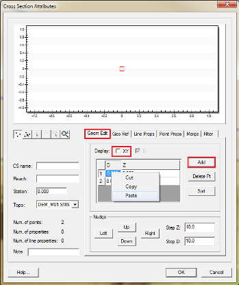
- Click on Add button and enter 2 for number of points which will initiate the data entry mode. Click OK.
- In row 1 under column named D, right click and select paste. You should see the cross section plot update itself.
- Click OK twice.
- Repeat the same process for rest of the other ds arcs (i.e. ds2, ds3, ds4, ds5 and ds_weir). Use the corresponding .csv files from \Module_Data\Module_04\xs\ folder to get the cross section information.
- Now since we modified these cross sections, we need to map the materials again. Right click on the Cross_Sections coverage one more time and select Map Materials from Area Coverage to map Manning's roughness values in each modified cross sections. Change Default Material to be Vegetated Creek. Click OK.
- Save your SMS project as \Module04.sms

In this section, we imported the cross section arcs from a shapefile to SMS and then extracted elevations. Let's proceed with the turorial to define 1D Channels.