Tute M04 MI 2d code Archive
Introduction
As with the breaklines, this can be done in two different layers. The 2d_code format can be used, this type of layer was used in module 1 to define the active area. The polygon has only one attribute that is an integer value 0 for inactive and 1 for active.
As we have the "HX" lines in the 2d_bc we can also create the polygon in this layer. This is the method which is outlined below. As we have changed the downstream boundary configuration, we also need to revise our active code layer.
Method
-
Firstly we will update the active 2D model area near the downstream boundary.
- Save a copy of 2d_code_M01_002 as 2d_code_M04_001. Open this layer and make it selectable.
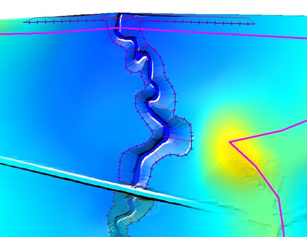
- Zoom into the downstream area of the model. There is a gap between the HX boundaries (1D/2D boundaries) and the active code area. If we leave the model with this configuration, water will not be able to leave enter the 1D model from the floodplain. The area is shown in the image below.
- Ensure that the 2d_bc_M04_HX_001 layer is open. Make sure this layer is selectable (but not editable).
- Make sure that snapping is turned on.
- Select the polygon in the 2d_code_M04_001 layer and select the reshape tool from the toolbars (
 ).
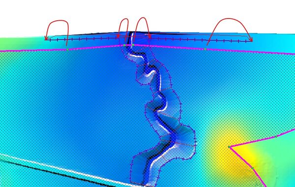
). - Move the four vertices on the code polygon so that they snap to the vertices on the "HX" lines as shown in the image below.
- Save the 2d_code_M04_001 layer and export this into .MIF format.
- Next we will create a polygon to deactivate the 2D cells in the creek area. Make sure the 2d_bc_M04_HX_001 is editable.
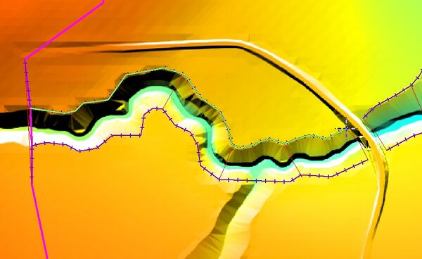
- Create a new polygon. Essentially we want to snap the line to each vertex on HX line to enclose these into a polygon. Fortunately we don't need to do this manually! Snap the first vertex to the end of one the "HX" line. To trace the HX line hold the "shift" key and then move the cursor to the other end of the HX line. The polygon should be tracing the line as shown below.
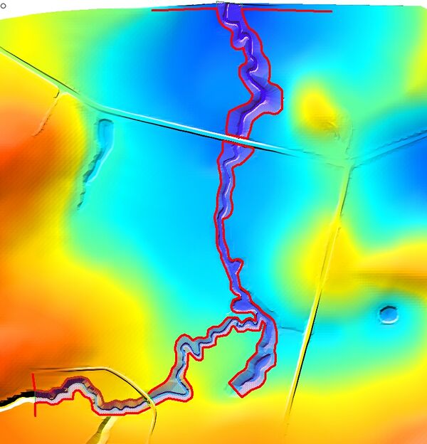
- Create three polygons that enclose the areas modelled in 1D. Note that at the road embankment, as we have not included a 1D weir, we will be modelling any overtopping in 2D and the polygon should not cover the road area.
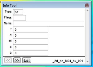
- For each of the polygons, set the "Type" to "CD" and the "f" attribute to 0.
- Save the 2d_bc_M04_HX_001 layer and export this into .MIF format.
Conclusion
We have modified the active model area 2d_code_M04_001 and also modified the boundary file to null the cells within the 1D model area. Both layers are now ready for input to our TUFLOW model. Return to the tutorial where the next step is to define the revised boundary conditions.