Tute M04 SMS 1d bc Archive
In Module02, the inflow hydrographs were put into the 2D BC and the outflow WSE Vs Flow (HQ) was defined at 2D BC as well. In this model, we will put the inflow hydrograph into the 1D channel. On the downstream side, the 1D part has been extended beyond the 2D domain and a different BC will be defined at the downstream end. We will assume that upon exiting the 2D domain water will go back into the 1D channel. So, there will be no downstream BC on the 2D domain where as on the 1D domain, we will use a 1D weir. If we were to let water exit the 2D domain independently, we would need to set the downstream boundary on 2D domain little differently which is not covered in this tutorial.
Inflow BCs
There are three inflow locations in the model, two at the upstream ends of the channel as QT boundary and one on the eastern part of the model as SA boundary. Both QT boundaries will be defined on 1D where as SA will be defined on 2D domain respectively.
Remove old BC
Before we proceed, let's remove the 2D inflow BC defined in Module02.
- Click on BC coverage.
- Click on Select Feature Arc tool and double click on the arc shown in the following figure.
- In the Boundary Conditions dialog that opnes, change BC Type to No BC and click OK.

Define new inflow BC
- Right click Map Data folder on the project explorer and create a new coverage. Coverage Type - TUFLOW | 1D/2D BCs and Links, Coverage Name 1D_BC.
- Make sure the coverage you just created 1D_BC is active. Click on Create Feature Point tool.
- Click on the locations shown in the following figure to create inflow nodes. Make sure they snap to the node on 1DCreek coverage.
- Click on Select Feature Point tool and double click the node on Eastern tributary. Set the following:
- Node Type: 1D
- Type: Flow vs Time (QT)
- Events: 100year
- Click on Curve Undefined button to open the XY series Editor window.
- Outside SMS, open an Excel spreadsheet \Module_Data\Module04\BC.xls. Copy the data in columns A and Column B and paste it on XY Series Editor window in SMS.
- Click OK twice.
- Repeat same steps for the node on western tributary. Copy data from column C and Column D in the file \Module_Data\Module04\BC.xls and paste in the XY Series Editor window.
- Click on BC coverage to make it active. We will define another inflow in this coverage.
- You should be able to see an area enclosed by a circular arc on the eastern past of the model. Click on Select Feature Polygon tool and double click inside this circular area.
- Check to make sure that a Flow Vs time BC has been defined and click on 100 year storm event to see the inflow hydrograph. This inflow hydrograph was already defined in Module02. If the BC is missing hydrograph, copy and paste from the file \Module_Data\Module04\BC.xls, columns E and F.

Outflow BCs
As previously discussed, the water will exit the model only from the 1D domain.
-
Let's first make sure the outflow BC on 2D domain has been removed.
- Click on BC coverage to make it active.
- Click on Select Feature Arc tool and double click on the arcs shown in the following figure. Change the BC's as indicated. Please note that these arcs are supposed to have HQ boundary with water surface slope of 0.01.
- Click on 1D_BC coverage to make it active.
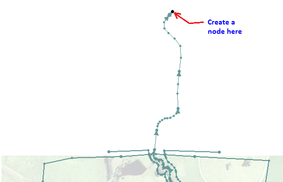
- Click on Create Feature Point tool and create a point at the most downstream end of the channel. See the following figure.
- Click on Select Feature Point tool and double click the node. Set the following:
- Node Type: 1D
- Type: WSE vs Flow (HQ)
- Events: 100year
- Click on Curve Undefined button to open the XY series Editor window.
- Outside SMS, open an Excel spreadsheet \Module_Data\Module04\BC.xls. Copy the data in columns G and Column H and paste it on XY Series Editor window in SMS.
- Click OK twice.
- Click OK.
- Save the SMS project.

Now let's define BC on 1D domain

Conclusion
Now we have defined all the boundary conditions in the model. Next step is to set up Simulation control files.