Tute M04 SMS 1d nwk Archive
In this section, we will create 1D channels. A 1D channel basically represents the channel thalweg and has to intersect the cross section arcs we created in the previous section. These 1D network arcs should also snap to the existing vertices in the cross section arcs.
Create 1D Channel
We will import a shapefile which shows the location of the channel thalweg. We will use this as a guide and create the channel manually.
- In SMS select File|Open. Browse and open file \Module_Data\Module04\1d_nwk_M04_channels_001_L.shp. This will add a GIS layer in the project explorer as well as display the channel thalweg in SMS main window.
- In the project explorer, right click on "Map Data" folder and select New Coverage. Change the Coverage Type to TUFLOW | 1D Networks and Coverage Name to 1DCreek. Click OK to create a new coverage. Note: After creating this new coverage, it will be an active coverage by default. If the cross section arcs disappeared from the display, that means the display of inactive coverage is turned off in SMS display options. We will need to turn it on. Select Display | Display Options, click on Map tab on the left hand side and toggle on Inactive Coverage.
- Turn off the display of all the coverages except Culverts, Cross_Sections and 1DCreek. Turn off the scatter and change the transparency of Aerial photo to 60%.
- Zoom in to the lower left corner of screen (South West) which is the upstream end of the creek. Make sure you see the vertices in the cross section arcs. If the vertices are turned off, turn those on from the SMS display options.
- Make sure 1DCreek covearge is still active. Pick Create Feature Arc tool.
- Trace an arc right above the channel thalweg displayed from the shapefile.
- Make sure that you trace from upstream to downstream direction, SMS will dispaly an arrowhead on the arc to show the direction.
- Make sure that arc you trace snaps to the vertex at the middle of the cross section arcs. Snapping should be turned on by default. If it is turned on, as you approach a node or vertex while tracing, a red-cross appears suggesting a snapping point. Snapping can be turned on/off by pressing "s" on your keyboad.
- Once the arc snaps to the vertex on cross section, double click to end the line. That means you will create a separate segment of 1D channel between each cross section.
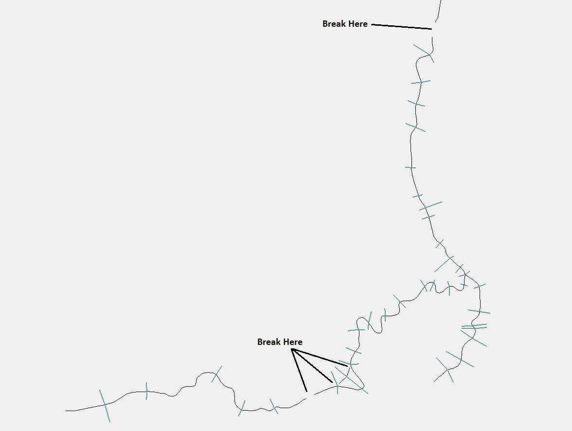
- There are few breaks in the 1D network lines, one on the left tributary, one near the bend near sixth cross section and one on the downstream segment. You should not trace the 1D arc between these two cross sections as there is a culvert and a weir connection at these locations.
- Make sure that the arc snaps to the ends of culvert at two culvert locations.
- You can scroll the mouse wheel to zoom in/out while tracing an arc. Similarly, you can click and hold the mouse wheel (at the middle) and pan around while tracing an arc.


Define Weir at Meander
On the section downstream of the culvert, there is an alternative flow path over a meander in the channel. We will define a weir channel in this area and connect it to the main channel. See the image below.
- Create an arc to represent the weir (shown by purple arc in the above figure). Notice that the weir arc snaps to a cross section at the middle and extends to the third cross section at the junction (do not end the 1D weir arc at the cross section at the middle). Make sure to draw from upstream to downstream direction.
- From the ends of the weir arc draw arcs to connect to the main channel. Look for yellow colored arcs in the above figure. Also watch for the direction of the connections. The connection at upstream end of weir is directed in opposite direction of flow where as that at the downstream end has same direction as the flow.
- Click on Select Feature Arc tool and double click on the Weir arc (purple colored in above figure). Change its type to be Weir. Click OK.
- Double click both the connector arcs (yellow colored in above figure) and change their type to Connection.

Define Weir at right tributary
Keep tracing all the acrs between cross sections. When you reach the confluence, start from the upstream end of other tributary which is at the lower right end of the screen.
- On the right tributary, trace all the 1D segments. Look at the following image carefully that the channel segment where the weir is defined begins at a cross section, has a cross section at the middle and ends at the third. While creating this 1D Weir segment, make sure to snap at the cross section at the middle and not end the arc there.
- Fourth arc from the upstream end of this tributary will be defined as a weir. Using Select Feature Arc tool, double click this arc and change its type to Weir. Click OK.

Define Weir at most downstream section
Continue downstream from the confluence until you reach the most downstream end (top of the screen).
- The most downstream segment of the 1D network should snap to the last cross section and should extend beyond. See the following image.
- Using Select Feature Arc tool, double click on this last segment of the 1D network and change it's type to Weir. Click OK.
- Save your SMS project

Verify 1D Culvert attributes
If you recall in the previous step, there were two locations where the 1D Channel arcs were not created. At these locations the creek is crossed by a road and a culvert has been defined in the base model (Turn on the display of Culverts coverage).
Similarly, the base model (from Tutorial Module02) has a number of 1D/2D links for the culverts. Now that we are modelling the entire creek in 1D we do not need to link the culverts in the creek to 2D domain because the 1D open channel and the 1D culverts are connected already based on their snapping. The third culvert FC04.1_C however is still embeded in the 2D grid and we will need to define a 1D/2D link.
- Click on Culverts coverage and zoom around each culvert.
- Click on Select Feature Arc tool and double click on each of the culvert arcs to open an attribute dialog.
- Verify the attributes defined for each culvert match the following table.
- Click on the "Attributes" Button to bring up the culvert attributes dialog.
- Verify the attributes defined for each culvert match the following table.
- Select OK twice to exit the Culvert/Weir Attributes dialog.

| Culvert | FC01.1_R | FC04.1_C | FC01.2_R |
|---|---|---|---|
| Type | Rectangular | Circular | Rectangular |
| Ignore in Computations | Not Selected | Not Selected | Not Selected |
| Use Channel Storage at Node | Selected | Selected | Selected |
| Manning's n | 0.015 | 0.015 | 0.015 |
| Upstream Invert | 44.6 | 43.35 | 37.8 |
| Downstream Invert | 44.5 | 42.85 | 37.5 |
| Form or Bend Losses | 0 | 0 | 0 |
| Blockage (%) | 0 | 0 | 0 |
| Attributes | |||
| Width | 1.8 | -- | 2.4 |
| Height | 1.8 | -- | 1.2 |
| Diameter | -- | 1.2 | -- |
| Number of Barrels | 3 | 3 | 5 |
| Contraction Coefficient - Height | 0.6 | -- | 0.6 |
| Contraction Coefficient - Width / Diameter | 0.9 | 0.9 | 0.9 |
| Entry Losses | 0.5 | 0.5 | 0.5 |
| Exit Losses | 1 | 1 | 1 |
1D/2D Connection for Culvert FC04.1_C
Since culvert FC04.1_C is embeded in 2D grid, we will need to define 1D/2D connection so that TUFLOW can transfer flow between the grid and 1D networks.
To define connection:
- Make sure that Culverts coverage is still active. Click on Select Feature Point tool.
- Double click on the upstream node of culvert arc FC04.1_C. This will open a Node Atrributes dialog.
- Towards the lower portion of this dialog, Create connection to 2D doamin (SX) should already be selected as was set up in Module02. If it is not selected, go ahead and toggle it on. Select Don't alter cell Z and click OK.
- Repeat the same process at its downstream node also.
- Save your SMS project.
Clean Connections
As, we already mentioned, other two culverts (FC01.1_R and FC01.2_R) are connected directly to the 1D network and we do not need to define any connection.
- In the project explorer, right click coverages Culvert_Connections and Culvert_BC and delete them.
- Click on Select Feature Point tool and double click nodes at both ends of culverts FC01.1_R and FC01.2_R to make sure Create Connection to 2D Domain (SX) option has been toggled off.
Conclusion
The 1D network layers are now ready for input into TUFLOW. Save the SMS project and return to the tutorial where the next step is to define the 1d/2d connections.