Tute M06 Arc 1D bridge Archive
The following steps are used to create the replacement 1D bridge and weir - 1d_nwk - that will represent the bridge in the 1D domain. We will also modify the 2D domain and boundary condition layers.
Method
Modify 1D 2D Boundaries
Unlike the other two bridge modelling options, to include the bridge and weir in 1D, we need to modify our 1D/2D connections and 2D code layers at the bridge location, as introduced in module 4 deactivate 2d cells and define the boundary conditions. This modification is needed to null out the 2D cells over the road embankment as now the 1D weir that we will create will carry the flow over the road.
- Please copy the provided 2d_bc_M06_HX_001_L,2d_bc_M06_HX_001_P and 2d_bc_M06_HX_001_R layers located in Module_Data\Module_06\1D_2D_BC and paste them into the TUFLOW\model\gis folder. Review within the GIS should show that the 2D code and boundaries have been modified adjacent to the bridge as per the right figure below.
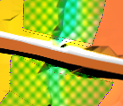
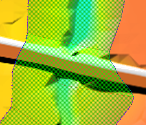
Caption: Bridge boundary configuration using 2d_bc_M04_HX_001* (left) and 2d_bc_M06_HX_001* (right)
Modify 1D Network
Now that we have modified the boundaries adjacent to the structure we can modify our 1d network. To implement the weir structure we need to create two new layers, a 1d_bg layer to define the weir geometry and a 1d_nwk layer to provide the location of the weir. To do this:
- Save a copy of the existing 1d_nwk_M06_bridge_001_L as 1d_nwk_M06_weir_001_L
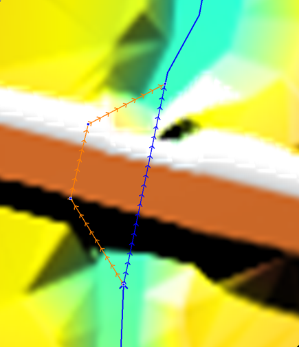
- Open 1d_nwk_M06_weir_001_L, make it editable and digitise a new channel from upstream to downstream at the bridge location, ensuring that the polyline is snapped to the 1d_nwk_M06_channels_001_L and 1d_nwk_M06_bridge_001_L nodes as shown below:
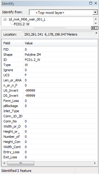
- Update the attribute table of the weir channel as per the below figure. Note that the W under the type attribute indicating a weir channel. The -99,999 for the upstream and downstream inverts will use the bed invert of the weir cross section. For more information on the varying other options please refer to the TUFLOW Manual.
- Delete the existing bridge channel from the 1d_nwk_M06_weir_001_L layer. This is not essential as the bridge will be defined by the last Read GIS Network command in the ecf however, it is good practice to not have duplicates when modelling.
- We will now define the layer that will link to our 1D weir cross section. Save a copy of the existing 1d_bg_M06_bridge_001_L as 1d_bg_M06_weir_001_L
- Open 1d_bg_M06_weir_001_L, delete the existing bridge polylines and digitise a new polyline that intersects the 1d_nwk_M06_weir_001_L layer as below. When digitised as a 2-point line, the 1d_bg layer does not need to snap to a vertex of the 1d_nwk layer.
- The broad crested weir geometry is defined in a separate csv file which is referenced as follows:
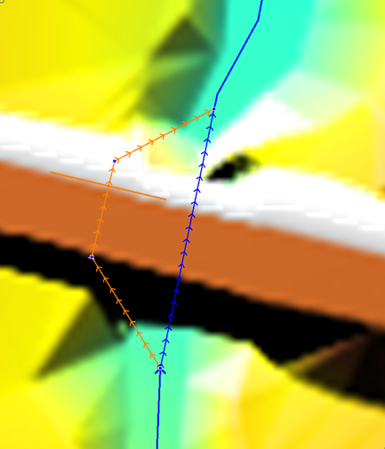
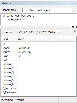
The XZ attribute says its in distance-elevation format. The XZ type cross section is easier to use here (when compared to the bridge HW table) as we don't need to allow for any pier blockage. We have provided the weir geometry file xs_weir.csv in your tutorial data. Please copy this into the TUFLOW\model\bg folder.
Congratulations, you now have modified the 1d network to include 1d weir overflow.
Conclusion
For Bridge Modelling Option 2, our 2D domain and 1D/2D boundary conditions have been modified and we have added a 1D weir and geometry to model high flows over the road embankment. To prepare the final bridge modelling approach please return to the main page of module 6.