Tute M06 MI 1D2D bridge Archive
Jump to navigation
Jump to search
The following steps are used to create the replacement 1D bridge channel - 1d_nwk - that will represent the bridge in the 1D domain.
Method
- Make a copy of the layer 1d_nwk_M04_culverts_001 located in the TUFLOW\model\mi folder and save as 1d_nwk_M06_bridge_001.
- Add the newly saved layer to the Mapinfo window and start editing. Right click on the 1d_nwk_M06_bridge_001 layer in the layer control and click browse table.
- Locate the entry for the feature labelled with ID FC01.2_R. Select the other features within the layer and delete the selected features. Only the feature with ID FC01.2_R should remain. (To select a feature/object while browsing a table, click on the blank space at the far left-hand side of each row. To delete the feature/object, simply hit delete).
- Update the attributes of the remaining feature as follows. Similar to the open channel developed in Tutorial M04, setting the upstream and downstream invert attributes to -99,999 means that TUFLOW will take the elevation values from the the cross section (or, in this case, bridge section, attached to the line). Note that Type B stands for Bridge.
- Note that the data entries for the other attributes are not used for the Bridge type structure (Len_or_ANA, n_or_n_F, Width_or_D, Height_or_, Number_of, Height_Con, Width_Cont, Entry_Loss and Exit_Loss). However, to avoid confusion it is recommended that these other attributes be cleared. Delete the data entries for the other attributes not used for the Bridge type structure.
The in-channel structure has been changed to a bridge by updating the feature FC01.2_B. We have created a 1d_nwk layer for the new bridge channel.
Save and export your edits. - Copy the ‘bg’ folder (and contents) located in Module_Data\Module_06\1D_Bridge and paste it in the TUFLOW\model\ folder. This folder contains the bridge cross section csv file, bridge form loss csv file and the GIS layer that connects the bridge cross section to the 1d_nwk_M06_bridge_001 layer. It also contains the weir geometry csv that we will use later for Bridge Modelling Option 2.
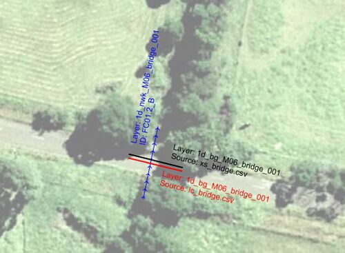
- Open the 1d_bg_M06_bridge_001 layer in MapInfo and use the info tool to observe the attributes. The 1d_nwk and 1d_bg layers are pictured below. The two polylines intersect the 1d_nwk feature. The Source attribute controls the data used to define the bridge cross section (type 'XZ', shown in black) and loss coefficient table (type 'LC', shown in red). Note that there is no need to define the elevation of the bridge soffit. TUFLOW will automatically assume this is the highest (last) elevation within the cross section table.
- Make a copy of the layer 1d_nwk_M04_culverts_001 and save as 1d_nwk_M06_culverts_001 in the TUFLOW\model\mi folder.
- Open the newly saved table file and start editing. Use the info tool to locate the feature with ID FC01.2_R. Select and delete the feature (we just created a bridge in this location to replace the culvert). Two structures should now remain, which will not be changed. We now have two 1d_nwk layers, one with just the new bridge (1d_nwk_M06_bridge_001) and one with the two remaining culverts (1d_nwk_M06_culverts_001). Note that you could include both the bridge and the culverts in the same 1d_nwk layer but it is common modelling practice to divide 1d_nwk layers up by structure type.
- Save your edits and export the 1d_nwk and 1d_bg layers.
| Attribute | Value |
|---|---|
| ID | FC01.2_B |
| Type | B |
| Ignore | F |
| UCS | T |
| US_Invert | -99999 |
| DS_Invert | -99999 |
 While we are replacing the culverts at one of the structures, we still need the other two culvert structures present in the model area. We are therefore going to create a copy of the 1d_nwk GIS layer containing the other culverts that can be read into the model.
Conclusion
The replacement 1D bridge and modified 1D culvert layers have been created to model the new bridge on the northern road. Please return to the main page of module 6.