XPSWMM Conversion Reconfigure SWMM Pipe Network Data
Correct SWMM Nodes--Junction/Outfall Model Design
XPSWMM used a modified version of the EPA SWMM engine. Unlike traditional EPA SWMM networks that require Nodes--Junctions at the upstream end of culverts and Nodes--Outfalls at the outlets, XPSWMM uses Nodes--Junctions in all locations. TUFLOW's implementation of SWMM has retained the traditional EPA SWMM structure. Due to this fundamental difference in approach, some manipulation of the Nodes--Junctions information is necessary.
- In the QGIS Layers panel, select (left click) Nodes--Junctions to make it the active dataset.
- Go to Processing > Toolbox from the top dropdown menu options to open the Processing Toolbox.
- Go to TUFLOW >> SWMM in the processing tool list and select 'Junctions - Downstream junctions to outfalls'. This opens the dialog shown below.
- Input Junctions: Nodes--Junctions (this will be prepopulated if Nodes--Junctions is the active dataset).
- Input Conduits: Click '...' and tick on Links--Conduits
- Modified Junctions Layer: Leave this field blank so the tool writes the data to a temporary file. It will not be used.
- Modified Outfalls Layer:
- Click '...', select 'Save to GeoPackage...'.
- Navigate to the TUFLOW\model\swmm folder and select the previously created HDR GeoPackage file. Click 'Save'.
- A dialog will open. In the 'Layer Name' field, write Nodes--Outfalls. It is important that this layer is named correctly so it is recognized by the other TUFLOW SWMM processing tools.
- Click 'OK'.
- Click 'Run'. Once the tool is finished, click 'Close'.
- The temporary junctions layer, Modified junctions layer, and the new outfalls layer, Nodes--Outfalls, will appear in the QGIS Layers panel.
- In the QGIS Layers panel, right click Modified junctions layer and select 'Remove Layer'.
- In the QGIS Layers panel, select (left click) Nodes--Outfalls and toggle off editing.
To complete the update process, it is necessary to remove the objects from Nodes--Junctions that coincide with the points created in Nodes--Outfalls. While this can be done manually, the steps below illustrate an automated process using a QGIS processing tool.
- In the QGIS Layers panel, select (left click) Nodes--Junctions and toggle on editing.
- Use the 'Select Features' tool to select all nodes included in the Nodes--Junctions layer. When selected, this will change their color to bright yellow.
- In the Processing Toolbox, go to 'Vector Selection' and select 'Select within distance'. This opens the dialog shown below.
- Select features from: Nodes--Junctions (this is prepopulated as Nodes--Junctions is the active dataset).
- By comparing to the features from: Click the dropdown menu and select Nodes--Outfalls.
- Where the features are within: '0.1 meters'
- Modify current selection by: 'selecting within current selection'
- Click 'Run'. Once the tool is finished, click 'Close'.
- In the QGIS Layers panel, right click Nodes--Junctions and select 'Open Attribute Table'.
- In the attribute table, only some of the junction nodes will be selected. Select 'Delete selected features' to delete these nodes. Close the attribute table.
- Toggle editing off to save the edits to Nodes--Junctions.
1D/2D Pipe Network Pit (Inlet Usage) Connections
Inlet usage connections establish the 1D/2D linkages between the ground surface, defined in 2D, and the 1D SWMM pipe network. Physically, these features come in various forms and dimensions; however, they are commonly referred to as kerb inlets, with or without associated grates. An example is shown in the image below.

The transfer of inlet usage connection information from XPSWMM to TUFLOW involves a three-step process:
- Export data from XPSWMM.
- Convert the exported data into a TUFLOW SWMM compatible format.
- Make minor edits to correct for snapping deficiencies in the XPSWMM export tools.
Export Data from XPSWMM
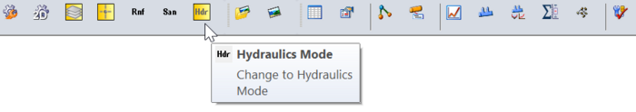
- In XPSWMM, select 'Hydraulics Mode' from the toolbar.
- In the XPSWMM Layers panel, right click Nodes and select 'Export To GIS File...'. This will open a dialog.
- Select the GIS File: Click the '...' and navigate to the TUFLOW\model\swmm folder. Enter an appropriate filename and set the file type to MapInfo Interchange File (*.mif). For example, 1D2D_Urban_Node_Export_001.mif.
- Click 'Node Data and Results' to expand the folder tree. Go to Node Data and Results > Hydraulics Node > HDR Node Data. Double click to select the following items:
- Node 2D Inflow Capture Flag
- Ground Elevation (Spill Crest)
- 2D Inflow Capture Coefficient
- 2D Inflow Capture Exponent
- In the right-hand table, the items above, along with 'Node Name', 'Node X' and 'Node Y', should be displayed.
- In the 'Custom Name' column, double click 'Ground Elevation (Spill Crest)' and update the name to Ground Elevation. This is necessary because the parentheses can cause issues with some GIS software.
- Click 'Export'. A message will appear reporting how many nodes were exported.

Convert Exported Data into TUFLOW SWMM Format
- In Windows File Explorer, navigate to the TUFLOW\model\swmm folder. Drag and drop the node export .mif file (e.g. 1D2D_Urban_Node_Export_001.mif) into QGIS.
You may receive a message stating that there is no transform between the CRS of the .mif file and the CRS of the QGIS workspace. Ignore this message and close the pop up. This issue will be resolved in the following steps. - In the QGIS Layers panel, select (left click) the node export layer.
- In the Processing Toolbox, go to TUFLOW >> SWMM and select 'Convert - XPSWMM GIS inlet layers to SWMM'. Enter the following information into the dialog.
- GIS layer with inlet information: This is prepopulated as the node export layer is the active dataset.
- Inlet name field: 'NodeName'
- Inlet elevation field: 'GroundElevation'
- Inlet 2d capture flag field: 'Node2DInflowCaptureFlag'
- Inlet discharge equation coefficient field: '2DInflowCaptureCoefficient'
- Inlet discharge exponent field: '2DInflowCaptureExponent'
- Inlet connection width: This defines the length used to assign the number of 2D cells associated with the 1D/2D connections. A value of 4m will be used in this example. This will select a single 2D cell for the connection.
- CRS: Select the models' Coordinate Reference System (CRS). For the demonstration model, the CRS is 'EPSG:32760 - WGS 84 / UTM zone 60S'.
- SWMM inp file (for inlet definition and curves):
- Click '...', and select 'Save to File...'.
- Navigate to the TUFLOW\model\swmm folder. Choose an appropriate .inp file name. For example, swmm_inlet_curves_XP_001.inp. This tool will also create a .gpkg file with the same data and name; saved in the same file location (e.g. swmm_inlet_curves_XP_001.gpkg).
- Click 'Save'.
- GeoPackage file for inlet usage:
- Click '...', and select 'Save to File...'.
- Navigate to the TUFLOW\model\swmm folder. Choose an appropriate .gpkg file name. For example, swmm_iu_XP_001.gpkg.
- Click 'Save'.
- Click 'Run'. Once the tool is finished, click 'Close'.
- In the QGIS Layers panel, right click node export layer and select 'Remove Layer'.
- In Windows File Explorer, navigate to the TUFLOW\model\swmm folder. Drag and drop the two new GeoPackage databases (e.g. swmm_iu_XP_001.gpkg and swmm_inlet_curves_XP_001.gpkg) into QGIS (hold Ctrl to select multiple). Inspect the attributes associated with the objects in both GeoPackages.
Edit TUFLOW SWMM Data
Unfortunately, the snapping tolerance set by XPSWMM for its Node GIS Data Export function is larger than the underlying EPA SWMM model information it is associated with. This can cause a slight offset in the data. To rectify this issue, we will use a processing tool designed to assist in this task.
- In the QGIS Layers panel, select (left click) the inlet usage layer (e.g. swmm_iu_XP_001) and toggle on editing.
- In the Processing Toolbox, select the 'Edit Features In-Place' tool
 . This allows the editing of an existing layer, instead of the creation of a new layer.
- Go to 'Vector geometry' in the processing tool list and select 'Snap geometries to layer'. This opens the dialog shown below.
- Reference Layer: Nodes--Junctions. This is the layer we want the inlet usage layer to snap to.
- Tolerance: '0.1 meters'
- Behavior: 'Prefer aligning nodes, don't insert new vertices'
- Click 'Modify All Features'. Once the tool is finished, click 'Close'.
- Toggle off the editing for the inlet usage layer (e.g.swmm_iu_XP_001) to save the edits.
Edit 1D/2D Culvert Connections
In addition to the pipe network inlet usage 1D/2D connections, we also need to connect the 1D culvert inlet/outlets to the 2D. These features are typically associated with culverts located under raised roads or rail embankments, outlets from pipe networks into creeks, streams, or rivers, or open pipe network inlets and outlets linked to major stormwater drainage infrastructure, which often involves the modification of historically above-ground streamflows to an underground stormwater network. An example is shown in the image below.

In order to connect a 1D SWMM culvert to TUFLOW 2D, TUFLOW SWMM necessitates 1D/2D HX connection lines at the upstream (inlet) end of the culvert and 1D/2D SX connection lines at the downstream (outlet) end. This model schematization matches the traditional requirements of EPA SWMM, though differs from that of XPSWMM, which require 1D/2D SX connections both upstream and downstream.

In the Convert XPSWMM Model to Recommended TUFLOW Structure section, the XPSWMM 1D/2D connections were converted into TUFLOW format. However, since we have included and edited the SWMM data (HDR, inlet curves, and inlet usage GeoPackages), this connections layer needs to be updated. We need to change the upstream SX connections to HX connections, create new upstream CN lines, and ensure that the connections are snapped to the pipe network.
- In the QGIS Layers panel, within the TBC group, select (left click) the 2d_bc lines layer (e.g. 1D2D_Urban_001_2d_bc_L) and toggle on editing. This layer contains the converted XPSWMM 1D/2D connections.
- In the Processing Toolbox, select the 'Edit Features In-Place' tool . This allows the editing of an existing layer, instead of the creation of a new layer.
- Go to 'Vector geometry' in the processing tool list and select 'Snap geometries to layer'. Enter the inputs below in the dialog box.
- Reference Layer: Links--Conduits. This is the layer we want the 2d_bc connections layer to snap to.
- Tolerance: '0.1 meters'
- Behavior: 'Snap end points to end points only'
- Click 'Modify All Features'. Once the tool is finished, click 'Close'.
- This tool has ensured that the 2d_bc connections layer is snapped to the pipe network.
- In the top dropdown menu options, select View > Toolbars. Tick on 'Snapping Toolbar'.
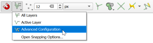
- Select the 'Enable Snapping'
 and 'All Layers > Advanced Configuration', an eye icon appears.
- Select the 'Edit Advanced Configuration'
 and tick on the 2d_bc_L connections layer and the Links--Conduits layer.
- From the 'Digitizing Toolbar', use the 'Add Line Feature' tool to add a CN line to each upstream Conduit connection.
- Draw the extra line between the upstream end of the Conduit and the end of the 1D/2D boundary line.
- Set the line 'Type' field to 'CN'.
- Leave the other attributes null and click OK.
- In the QGIS Layers panel, tick the drop down arrow next to the 2d_bc connections layer. This will display the colors associated with the different connection types.
- Use the 'Identify Features'
 tool to select an upstream 'SX' connection. A dialog will open.
- Change the 'Type' field to 'HX'.
- Repeat this for each upstream 'SX' connection.
- Toggle off editing for the 2d_bc connections layer to save the edits.
- Click the 'Apply TUFLOW Styles to Current Layer' button for a defined symbology to be applied to the HX lines (they may have gone translucent when you clicked Save).

| Up |
|---|
| Up |
|---|