Tutorial M02
Introduction
In the first part of this module, breaklines are added to ensure that the key hydraulic controls are correctly represented in the 5m cell size model. The second part involves simple and more complex development topographic modifications.
The GIS layers are:
- TGC layers:
- 2d_zsh: A layer used to modify Zpt elevations using points, lines and polygons.
- 2d_mat: A layer used to define the land use (material) types within the developmental area.
Module 2 builds from the model created in Module 1. The completed Module 1 model is provided in the Module_02\TUFLOW folder.
Part 1 - Breaklines
The first part of this module introduces breaklines for road crests.
There are a few ways to model breaklines based on the models cell size. The Shape_Width attribute controls the width of the breakline:
- Thin Breakline: Shape_Width equal to 0 - only elevations on the cell sides and cell corners are modified, no change in storage.
- Thick Breakline: Shape_Width less than or equal to 1.5 times the cell size - entire cells are modified, storage changes with changing elevation of the cell centres.
- Wide Breakline: Shape_Width greater the 1.5 times the cell size - any elevation points within a distance of half the Shape_Width attribute are modified, storage changes.
GIS Inputs
Create, import and view input data:
Simulation Control Files
TUFLOW Geometry Control File (TGC)
- Save a copy of M01_001.tgc as M02_001.tgc in the Module_02\TUFLOW\model folder.
- Open the M02_001.tgc in a text editor and add the following line after the 'Read GRID Zpts == grid\DEM.tif' command. Note, the points and lines are in separate layers, but are part of the same breakline, therefore they are input on the same line with a vertical bar '|' to tell TUFLOW the layers are linked. The TUFLOW modelling convention is to list the lines first and then points.
QGIS - SHP
Read GIS Z Shape == gis\2d_zsh_M02_rd_crest_001_L.shp | gis\2d_zsh_M02_rd_crest_001_P.shp ! Defines the road crest
QGIS - GPKG
Read GIS Z Shape == 2d_zsh_M02_rd_crest_001_L | 2d_zsh_M02_rd_crest_001_P ! Defines the road crest
- Save the TGC.
TUFLOW Control File (TCF)
- Save a copy of M01_5m_001.tcf as M02_5m_001.tcf in the Module_02\TUFLOW\runs folder.
- Open the file M02_5m_001.tcf in a text editor and make the following reference updates:
QGIS - SHP
Geometry Control File == ..\model\M02_001.tgc ! Reference the TUFLOW Geometry Control File
QGIS - GPKG
Spatial Database == ..\model\gis\M02_001.gpkg ! Specify the location of the GeoPackage Spatial Database
Geometry Control File == ..\model\M02_001.tgc ! Reference the TUFLOW Geometry Control File
- Save the TCF.
Running the Simulation
Run the model using a batch file. Batch files include a wide array of TUFLOW options and functions, such as running multiple simulations in series or parallel, testing model initialisation and even copying models for transfer between modellers or organisations. For more information, see Run TUFLOW From a Batch file.
- Save a copy of _run_M01_HPC.bat as_run_M02_HPC.bat in the Module_02\TUFLOW\runs folder.
- Open the _run_M02_HPC.bat in a text editor and update the text:
set exe="..\..\..\exe\2026.0.0\TUFLOW_iSP_w64.exe"
set run=start "TUFLOW" /wait %exe% -b
%run% M02_5m_001.tcf
- The 'set exe' command specifies the link to the TUFLOW executable. This file path may need to be changed depending on the folder set up.
- The 'set run' command contains a series of commands:
- start: Opens each simulation in a separate console window.
- "TUFLOW": Sets 'TUFLOW' as the title of the console window.
- /wait: If multiple simulations are to be run, it is often desirable to run these in series, i.e. the second simulation starts after the first finishes. The /wait switch makes the batch file wait until the process is finished before moving onto the next command.
- %exe%: executes tasks specified in the variable called ‘exe’, in this case the TUFLOW executable.
- -b: The use of the –b (batch mode) switch suppresses the need to press the return key at the end of a simulation. This ensures that one simulation proceeds on to the next without any need for user input. This is required for running multiple simulations in series (one after the other).
- The '%run%' executes tasks specified in the variable called ‘run’.
- The 'set exe' command specifies the link to the TUFLOW executable. This file path may need to be changed depending on the folder set up.
- Save the batch file and double click it in file explorer to run the simulation.
Troubleshooting
See tips on common mistakes and troubleshooting steps if the model doesn't run:
Check Files
While the model is running, check that the added features are specified correctly:
Results
For viewing of the 2D map results, see Module 1.
Suggestions for an investigation:
- Does the flooding still overtop the roads?
- Does the flooding still overtop the roads?
- Tip: check the maximum 2D results.
- What is the difference in peak water level at the upstream of the roads compared to the Module 1 run?
- What is the difference in peak water level at the upstream of the roads compared to the Module 1 run?
- Tip: Use the ‘Plot Time Series from Map Output’ tool in the TUFLOW Viewer QGIS Plugin.
- Or: Use the ‘Time Series’ tool in the TUFLOW Viewer 2 QGIS Plugin.
Part 2 - Other Topographic Updates
The second part of this module introduces a range of options to make both simple and complex topography modifications. It also introduces an additional materials file to reflect the changes of land use based on the complex topography modifications.
There are a few ways to create polygon topographic modifications based on the Shape_Option attribute:
- Merge - merges the elevations at polygon perimeter vertices with the topography Zpt values.
- No merge - assigns a single elevation to all Zpts falling within the polygon.
- Add - raises or lowers the polygon by a fixed value.
- TIN functionality - uses combination of points, lines and polygons to create complex topographic modifications.
GIS Inputs
Create, import and view input data:
Simulation Control Files
TUFLOW Geometry Control File (TGC)
- Save a copy of the M02_001.tgc as M02_002.tgc in the Module_02\TUFLOW\model folder.
- Open the M02_002.tgc in a text editor and add the following lines after the road crest input.
QGIS - SHP
Read GIS Z Shape == gis\2d_zsh_M02_fill_002_R.shp ! Defines areas of imported fill
Read GIS Z Shape == gis\2d_zsh_M02_merge_002_R.shp ! Defines areas of merging topography
Read GIS Z Shape == gis\2d_zsh_M02_cut_002_R.shp ! Defines excavation through embankment
Read GIS Z Shape == gis\2d_zsh_M02_landscape_002_R.shp | gis\2d_zsh_M02_landscape_002_L.shp | gis\2d_zsh_M02_landscape_002_P.shp ! Defines areas of complex landscaping
QGIS - GPKG
Read GIS Z Shape == 2d_zsh_M02_fill_002_R ! Defines areas of imported fill
Read GIS Z Shape == 2d_zsh_M02_merge_002_R ! Defines areas of merging topography
Read GIS Z Shape == 2d_zsh_M02_cut_002_R ! Defines excavation through embankment
Read GIS Z Shape == 2d_zsh_M02_landscape_002_R | 2d_zsh_M02_landscape_002_L | 2d_zsh_M02_landscape_002_P ! Defines areas of complex landscaping
As the points, lines and regions are in separate files, but are part of the same topographic modification, they are input on the same line with a vertical bar '|' to tell TUFLOW the layers are linked. The TUFLOW modelling convention is to list the polygons first, then lines and points last. - Add in the following line after the 'Read GIS Mat' command.
QGIS - SHP
Read GIS Mat == gis\2d_mat_M02_landscape_002_R.shp ! Sets the material values according to attributes in the GIS layer
QGIS - GPKG
Read GIS Mat == 2d_mat_M02_landscape_002_R ! Sets the material values according to attributes in the GIS layer
Assigns the updated materials values due to the development. As the order of commands in the TGC is critical, ensure this command is written after the original Read GIS Mat command. - Save the TGC.
TUFLOW Control File (TCF)
- Save a copy of M02_5m_001.tcf as M02_5m_002.tcf in the Module_02\TUFLOW\runs folder.
- Open the file M02_5m_002.tcf in a text editor and make the following reference updates:
QGIS - SHP
Geometry Control File == ..\model\M02_002.tgc ! Reference the TUFLOW Geometry Control File
QGIS - GPKG
Spatial Database == ..\model\gis\M02_002.gpkg ! Specify the location of the GeoPackage Spatial Database
Geometry Control File == ..\model\M02_002.tgc ! Reference the TUFLOW Geometry Control File
- Save the TCF.
Running the Simulation
Update the batch file created in the first part of Module 2 to reference the M02_5m_002.tcf file. Save the batch file and double click it in file explorer to run the simulation.
Troubleshooting
See tips on common mistakes and troubleshooting steps if the model doesn't run:
Check Files
While the model is running, review the added features are specified correctly:
Results
For viewing of the 2D map results, see Module 1.
Impact Assessment
The asc_to_asc utility with difference flag is used to plot the flood level changes resulting from the topography updates. The utility is provided in the exe\asc_to_asc folder. It can also be downloaded from the TUFLOW website and saved into a folder with other utilities.
- Create a new batch file _M02_asc_to_asc_Level_Difference.bat in the Module_02\TUFLOW\results\grids folder and open it in a text editor.
- Input the following (Note: Utility location may differ):
set asc_to_asc="..\..\..\exe\asc_to_asc.2024-06-AF\asc_to_asc_w64.exe"
- Use the -dif flag to call the difference function. The utility then expects two grid files, it subtracts the first grid from the second. Add the following syntax below the 'set asc_to_asc' command.
%asc_to_asc% -b -dif M02_5m_002_h_Max.tif M02_5m_001_h_Max.tif
- Optional is to use the -out flag to specify the name of the output grids.
%asc_to_asc% -b -dif -out M02_Level_Difference M02_5m_002_h_Max.tif M02_5m_001_h_Max.tif
- Save the batch file and double click it in file explorer to run the utility.
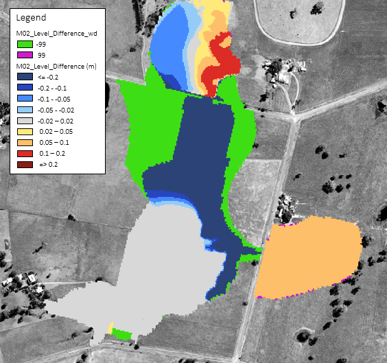
- The resulting difference grids appear in the same folder location, open these in a GIS software to see the effects of the topography changes on the flood levels.
- M02_Level_Difference.tif = difference in maximum flood level.
- M02_Level_Difference_wd.tif = change in flood extent, identifying cells that were once wet, now dry (-99) and once dry, now wet (99).

Conclusion
- Breaklines and different polygon topographic modifications were added to the model.
- Check files were assessed to view the changes on the underlying topographic model.
- Impact assessment was conducted using the asc_to_asc utility.
- For further training opportunities see TUFLOW Training Catalogue and/or contact training@tuflow.com.
| Up |
|---|