Difference between revisions of "1D Culverts"
Rohan.king (talk | contribs) |
Rohan.king (talk | contribs) m (→Check Files) |
||
| Line 49: | Line 49: | ||
[[File:TSF_result_file.JPG|border|600px]] | [[File:TSF_result_file.JPG|border|600px]] | ||
| − | = | + | =Typical check files used= |
The table below highlights some of the commonly used check files when reviewing 1D culverts. The full list of TUFLOW check files can be found [[TUFLOW_Check_Files | here]]. <br> | The table below highlights some of the commonly used check files when reviewing 1D culverts. The full list of TUFLOW check files can be found [[TUFLOW_Check_Files | here]]. <br> | ||
Revision as of 03:14, 10 February 2016
Page Under Construction
Introduction
- Advice on SX connections & number of cells to connect to 2D domain – implications
- Flow regimes – theory behind each.
- How to check for the flow regime – link to check file
- How do we sub divide logic rules (operational culverts)*
- Losses – fixed, Englehund, automatic manholes etc.
- Provide some justification on the ‘default’ height/width, entry/exit losses.
Flow Regimes
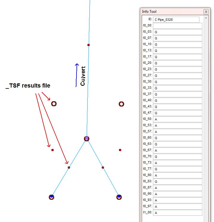
The flow regime through a culvert are divided into the following types. Checking this information for any 1D culvert can be inspected from the _TSF.mif/_TSF_P.shp that outputs the regime at each output interval.
| Regime | Description |
|---|---|
| A | Unsubmerged entrance and exit. Critical flow at entrance. Upstream controlled with the flow control at the inlet. |
| B | Submerged entrance and unsubmerged exit. Orifice flow at entrance. Upstream controlled with the flow control at the inlet. |
| C | Unsubmerged entrance and exit. Critical flow at exit. Upstream controlled with the flow control at the culvert outlet. |
| D | Unsubmerged entrance and exit. Sub-critical flow at exit. Downstream controlled. |
| E | Submerged entrance and unsubmerged exit. Full pipe flow. Upstream controlled with the flow control at the culvert outlet. |
| F | Submerged entrance and exit. Full pipe flow. Downstream controlled. |
| G | No flow. Dry or flap-gate active. |
| H | Submerged entrance and unsubmerged exit. Adverse slope. Downstream controlled. |
| J | Unsubmerged entrance and exit. Adverse slope. Downstream controlled. |
| K | Unsubmerged entrance and submerged exit. Critical flow at entrance. Upstream controlled with the flow control at the inlet. Hydraulic jump along culvert |
| L | Submerged entrance and exit. Orifice flow at entrance. Upstream controlled with the flow control at the inlet. Hydraulic jump along culvert. |
Example of the _TSF results in GIS:

Typical check files used
The table below highlights some of the commonly used check files when reviewing 1D culverts. The full list of TUFLOW check files can be found here.
| Filename prefix / suffix | Brief Description |
|---|---|
| _inverts_check.mif _inverts_check_P.shp |
Contains the inverts of the 1D nodes and at the ends of the 1D channels. Very useful for checking for smooth transitions from one channel to another and with the nodes. |
| _iwl_check.mif _iwl_check_P.shp |
GIS .mif/.mid or .shp files of the initial water levels at the 1D model nodes. |
| _nwk_C_check.mif _nwk_C_check_L.shp |
GIS .mif/.mid or .shp files of the final 1D model network. This check layer contains the channels of the 1D domain only. The _nwk_N_check layer contains the nodes. The layers lines are coloured based on the channel type (available for the .mid/.mif format only). |
| _nwk_N_check.mif _nwk_N_check_P.shp |
GIS .mif/.mid or .shp files of the final 1D model network. This check layer contains the nodes of the 1D domain only. The _nwk_C_check layer contains the channels. The node symbology is displayed as a red circle for nodes connected to two or more channels, a larger magenta circle for nodes connected to one channel and a large yellow square for nodes not connected to a channel (available for the .mid/.mif format only). This is very useful for checking for channel ends or nodes that are not snapped. |
Any further questions please email TUFLOW support: support@tuflow.com