1D Bridges: Difference between revisions
| Line 14: | Line 14: | ||
:*automatically simulates pressure flow conditions. The only loss coefficients required to be specified for BB channels are those due to piers, and the bridge deck when it is submerged and not under pressure flow. |
:*automatically simulates pressure flow conditions. The only loss coefficients required to be specified for BB channels are those due to piers, and the bridge deck when it is submerged and not under pressure flow. |
||
Note: |
Note: Adjustment of losses according to approach/departure velocities is the default from 1D channel to 1D bridge to 1D channel. However, for TUFLOW Builds prior to 2020-10-AA, if the BB bridge is linked directly to a 2D domain (typically via a SX link), there is no adjustment of entrance / exit losses on the sides connected to the 2D. This capability was introduced for 2D channel to 1D bridge to 2D channel in Build 2020-10-AA and onwards, and losses can be automatically adjusted based on the approach/departure 2D velocities across the SX connections by setting "<font color="blue"><tt>Structure Losses SX</tt></font> <font color="red"><tt>==</tt></font><tt> ADJUST</tt>". For B bridges the default is not to adjust losses (please refer to the <u>[https://downloads.tuflow.com/_archive/TUFLOW/Releases/2018-03/TUFLOW%20Manual.2018-03.pdf 2018 TUFLOW Manual]</u> for more information). In the case of 2D connections, refer to the links below for a discussion on the intricacies and challenges of taking into account contraction and expansion losses for 1D structures connected directly to 2D domains: |
||
| ⚫ | |||
| ⚫ | |||
| ⚫ | As a typical rule-of-thumb, if the channel upstream and/or downstream of the bridge is modelled in 1D then the bridge should also be modelled in 1D. Ideally, any change in the channel from ESTRY 1D to 2D or vice-versa should also occur at a structure (i.e. bridge, culvert, etc) to facilitate the transition in solution schemes. The images below displays a typical preferred setup, however as is the case with hydraulic modelling your particular model situation may be different and therefore not always conform to these ideals.<br> |
||
| ⚫ | |||
| ⚫ | |||
| ⚫ | As a typical rule-of-thumb, if the channel upstream |
||
<div><ul> |
<div><ul> |
||
Revision as of 09:56, 3 January 2023
Page Under Construction
Introduction
The following section looks at bridges using the 1D component of TUFLOW. Reference should also be made to Section 5.7.2 of the 2018 TUFLOW Manual. For information on bridges in the 2D domain please see 2D Hydraulic Structures and Module 11.
1D bridge channels do not require length, Manning's n, divergence or bed slope (they are effectively zero-length channels in terms of conveyance) and rely on a reasonable estimate of energy losses associated with re-expansion of water after the vena-contracta (entrance losses), expansion of water downstream (exit losses), pier losses, bridge deck and guard rail losses. Other factors include accounting for occurrence of bridge deck pressure flow and the effects of bridge skew and multiple bridges (shielding effects of an upstream bridge on a downstream bridge).
Care must be taken when choosing the approach to modelling the bridge and setting appropriate loss values.
TUFLOW offers two 1D bridge channels, B and BB. BB channels were introduced for Build 2016-03-AA and are a more advanced solution than B channels, which are retained for legacy models. By default, BB channels are superior to B channels as they:
- adjust the entrance and exit losses every timestep according to the approach and departure velocities (in the same manner as for other structures such as culverts); and
- automatically simulates pressure flow conditions. The only loss coefficients required to be specified for BB channels are those due to piers, and the bridge deck when it is submerged and not under pressure flow.
Note: Adjustment of losses according to approach/departure velocities is the default from 1D channel to 1D bridge to 1D channel. However, for TUFLOW Builds prior to 2020-10-AA, if the BB bridge is linked directly to a 2D domain (typically via a SX link), there is no adjustment of entrance / exit losses on the sides connected to the 2D. This capability was introduced for 2D channel to 1D bridge to 2D channel in Build 2020-10-AA and onwards, and losses can be automatically adjusted based on the approach/departure 2D velocities across the SX connections by setting "Structure Losses SX == ADJUST". For B bridges the default is not to adjust losses (please refer to the 2018 TUFLOW Manual for more information). In the case of 2D connections, refer to the links below for a discussion on the intricacies and challenges of taking into account contraction and expansion losses for 1D structures connected directly to 2D domains:
As a typical rule-of-thumb, if the channel upstream and/or downstream of the bridge is modelled in 1D then the bridge should also be modelled in 1D. Ideally, any change in the channel from ESTRY 1D to 2D or vice-versa should also occur at a structure (i.e. bridge, culvert, etc) to facilitate the transition in solution schemes. The images below displays a typical preferred setup, however as is the case with hydraulic modelling your particular model situation may be different and therefore not always conform to these ideals.
-
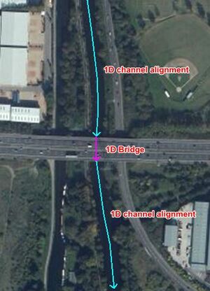
1D channel to 1D bridge to 1D channel -
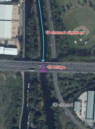
1D channel to 1D bridge to 2D channel -
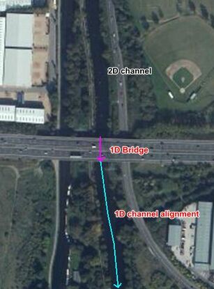
2D channel to 1D bridge to 1D channel


Example of a bridge that could be modelled in 1D

London, UK (pht: Rohan King)
Loss Theory
Contraction/Expansion Losses
Energy loss is caused by the flow contraction due to the expansion of water after the vena-contracta inside a bridge section and the flow expansion downstream the bridge. The contraction/expansion loss coefficients (or the entry/exit loss coefficients) can be specified for TUFLOW 1D BB bridge using the following attributes:
- EntryC_or_WSa: the entry loss coefficients (default = 0.5).
- ExitC_or_WSb: the exit loss coefficients (default = 1.0).
Note that the entry/exit loss coefficients are adjusted based on the equations in the figure below to consider the extent of flow contraction/expansion. For example, a clear spanning bridge over a stormwater channel does not cause any contraction/expansion. The change in approach velocity, structure velocity and the departure velocity are effectively the same, the loss coefficients can be automatically reduced based on the following equations.

The entry/exit loss coefficients are not used in the legacy B bridge. Instead, the bridge opening ratio is used to obtain the backwater coefficient Kb value from Figure 6 "Backwater coefficient base curves" of Hydraulics of Bridge Waterways (Bradley, 1978).
Pier Losses
Peir loss coefficients are treated as a direct energy (form) loss and can be derived from information in publications such as Hydraulics of Bridge Waterways (FHA, 1978 or AUSTROADS, 2019).
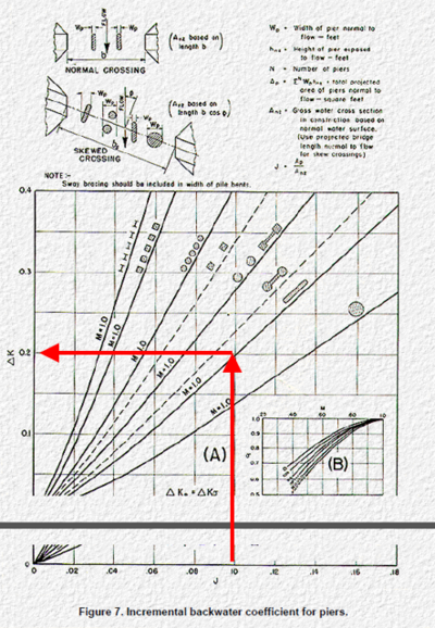
Energy loss estimates from bridge piers or other obstructions, vertical or horizontal, that do not cause upstream controlled flow regimes like pressure flow, are dependent on the ratio of the obstruction's area perpendicular to the flow direction to the gross flow area of the bridge opening, the shape of the piers or obstruction, and the angularity of the piers/obstruction to the flow direction. For example, using FHA (1978) the approach is:
- Calculate the ratio of the water area occupied by piers to the gross water area of the constriction (both based on the normal water surface) and the angularity of the piers. These inputs are used to calculate "J" in the FHA documentation.
- Use the FHA (1978) Incremental Backwater Coefficient for Piers data to calculate Kp. This is the value that will be entered into the bridge's LC (loss vs height) table as the energy or form loss coefficient. For piers or obstructions that are non-uniform in dimensions or shape the LC table can be used to vary the losses with height accordingly noting that losses will need to be proportioned with depth to reflect the combined effect of the different obstruction shapes/dimensions.
Deck Losses and Pressure Flow
When water level reaches the bridge deck level, extra energy loss can be caused by the bridge deck. It could result into pressure flow condition where water is force through a small opening confined by the bridge abutments and the deck. As the bridge becomes totally drawn, it will switch back to the normal flow condition with submerged bridge deck.
Once water commences to surcharge the bridge deck, TUFLOW BB bridge tests for pressure flow or drowned flow every timestep by choosing the flow regime that gives the lower flow:
- The pressure flow equation is based on the Section 8.3 "All Girders in Contact with Flow (Case II)" of the Hydraulics of Bridge Waterways (Bradley, 1978), with a default deck discharge coefficient of 0.8. This value can be modified using the 1d_nwk HConF_or_WC attribute. Note that the original hydraulic experiment conducted by Liu (1967) used a flume with a pair of bridge abutments and a deck. This means the impact of both abutments and deck are considered in this approach. The entry/exit losses are switched off during the pressure flow calculation to avoid the overestimation of the contraction/expansion losses.
- For the drowned flow condition, the BB bridge considers extra energy loss caused by the bridge deck/rails using a deck loss coefficient (default = 0.5) in addition to the entry/exit losses. The deck loss coefficient can be adjusted using the WConF_or_WEx attribute or by specifying the LC (energy loss versus height) table.
When pressure flow occurs a flow regime of "P" is reported in the _TSF layer.
For the legacy B channels, the deck loss coefficient was fixed at a value of 1.5625, which is derived from the discharge coefficient in Hydraulics of Bridge Waterways of 0.8 (1.56 = 1/0.8^2) to approximate pressure flow conditions. Whilst this is reasonable when the bridge deck experiences pressure flow, it will over-estimate the losses once the bridge deck starts to drown out and flow returns fully to downstream controlled.
Irregular shaped bridges
In the UK arch shaped bridges can often be seen on waterways, whereas in Australia these types of structures are quite uncommon. Modelling an irregular shaped bridge utilises the hydraulic properties elevation-width (CS/HW) type cross section and an irregular type culvert.
- Methodology
-
1. Create a 1d_tab HW (height vs width) .csv file for each standard shape (ie. set up a database of the irregular shapes). For the height value you can start at a value of zero so that height becomes depth (this might making the .csv files easier). As the height increases the width changes to reflect the particular irregular shape you are modeling. In the example below, the width at the top of the arch (2.1m) is set to a small value of 0.001m as opposed to zero as the HW becomes NA past the top of the irregular shape.

GIS example set up:

2. Any number of 1d_tab lines can reference the same .csv file, ie. you don't need to have a unique .csv file for every 1d_tab line.

3. One option is to copy and paste the 1d_tab lines across each pipe (if you use a two vertex 1d_tab line there is no requirement that the 1d_tab line is snapped to the 1d_nwk pipe line - they just need to intersect). Each line will need to reference the relevant standard irregular shape HW .csv file (this could be automated using SQL Select if you have an attribute on the pipe to indicate which irregular shape it is).
4. The inverts of the pipes should raise or lower the standard irregular shape cross-section to the appropriate height.
- Real world examples


London, UK (pht: Rohan King)
Typical check files used
The table below highlights some of the commonly used check files when reviewing 1D bridges. The full list of TUFLOW check files can be found here.
Any further questions please email TUFLOW support: support@tuflow.com
Back to 1D Hydraulic Structures