Tute M04 Arc 1d nwk Archive
Jump to navigation
Jump to search
Introduction
In this section we create the 1D channels. For this tutorial a number of completed channels are provided as a guide. If this was not provided, the method would be to copy the "1d_nwk_empty_L.shp" file from the TUFLOW\model\gis\empty folder and save this in the TUFLOW\model\gis\ folder, rename the file and begin the edits in this layer.
Method
- Ensure the cross-section layer is open.
- Copy the 1d_nwk_M04_channels_001_L and 1d_nwk_M04_culverts_001_Lfiles from the Module_Data\Module_04\gis\ folder and into the TUFLOW\model\gis\ folder you are working in. Open both files in ArcMap.
- Make both layers visible and begin editing the 1d_nwk_M04_channels_001_L layer.
- In the snapping toolbar make sure the snapping to points, end and vertex are enabled.
- Zoom in to the south western edge of the model, where the main inflow occurs.
- Digitise a polyline from the end of the channel provided, along the creek centreline, and double click on a vertex of the next cross-section downstream to finish the channel segment. Each channel (from cross-section to cross-section) is required to be a separate line object. Don't fill in the GIS attributes yet, we will fill these out at the end. Tip: Using a line style with an arrow at the end of the line makes it easy to see where one channel ends and the next begins.
- At the location of the 1st culvert (in the 1d_nwk_M02_culverts_001_L) we need to ensure that the channel snaps to the upstream of the culvert. At the downstream end of the culvert, ensure that start of the open channel is snapped to the end of the culvert. In these locations there are three layers snapped together: the culvert, channel and cross-section.
- The first two sections downstream of the culvert have been digitised in the layer provided. In this area there is an alternative flow path over a meander in the channel. A weir channel has been digitised in the layer provided. We need to connect this to the main channel. Digitise a line, from the junction of the channels to the upstream end of the weir, as shown in the image below.
- Enter "X" into the GIS attribute Type. This "X" or channel connector, connects the channels together but indicates that the weir is not the main channel path.
- At the downstream of the weir, enter another channel connector.
- Continue digitising channels between the cross-sections. At the second culvert ensure you snap to each end of the culvert. At the downtstream of the model, snap to the channel provided in the layer.
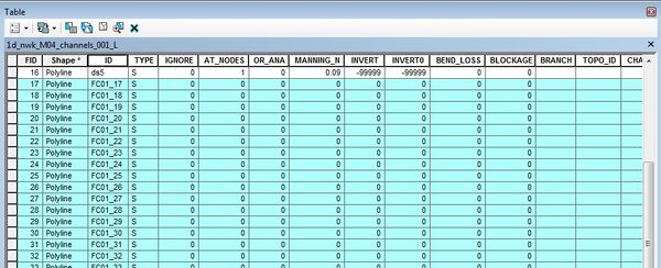
- Once all the the channel lines have been drawn we will update the GIS attributes. The first thing we need to do is select only the channels that do not have any attributes set. The channels provided as part of the module data already have the correct attributes. To select the channels without a Type assigned, we will use the query by attribute function in ArcMap. To access this, right click on the 1d_nwk_M04_chanel_001_L in the table of contents and select Open Attribute Table from the menu.
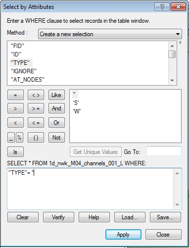
- At the top select the Query by attribute icon. In the dialogue we want to select any channels that have no Type attribute assigned. To do this double click on the "Type" in the top section, adding this to the selection query. Add the = symbol and then enter two single quotes to select blank channels. The final query is:
"TYPE" = ''
- In the browser window the blank channels should now be selected.
- We can now update this selection. To do this right click on the Type column and select field calculator. Set the expression to "S" and select OK. This step has updated all channels not yet assigned as the "S" type, which is the standard open channel type.
- Each channel in TUFLOW requires a unique ID. Typically this may be based on a naming convention based on the channel name / chainage. To make this easier in the tutorial model we will use the "feature ID" field [FID] to create a unique ID. Right click on the ID column in the table view and select field calculator. Enter the following:
"FC01_"& [FID]
- Repeat the update process to update the AT_NODES to 1 (for true). This tells TUFLOW to automatically calculate the storage at the nodes (ends of the channel) based on the cross-sectional properties and the channel length.
- Update the MANNING_N to 0.09 (don't use quotes because this is a numerical field). Set the INVERT (Upstream_Invert) and INVERT0 (Downstream_Invert) to -99999.
- Save the edits to the 1d_nwk_M04_channels_001_L layer and stop editing. This file is now ready for import into TUFLOW.


In Tutorial module 2 we created a number of 1D/2D links for the culverts. We did this in a number of ways, one of these was to create the link using a 1d_nwk layer (link to Module 2). Now that we are modelling the entire creek in 1D we need to remove these. As these links are created on the points objects we need only remove the reference to these in the control file. We will detail this in the section on updating the control files.
Conclusion
The 1D network layers are now ready for input into TUFLOW. Please return to the tutorial where the next step is to define the 1d/2d connections.