Tute M09 MI 2D2D domain Archive
Introduction
In this page we prepare the GIS inputs that define the coarse resolution (5m) and fine resolution (2.5m) domain areas, the external and internal boundary condition files associated with each domain and the boundary conditions files required to transfer flow between both domains.
NB: The following section assumes that you are proficient in the use of your chosen GIS package as details explaining 'how to' have not been included.
Module Data
Four separate GIS datasets have been provided in the Module_Data\Module_09 folder.
- FINEdomain_boundary.TAB
- 2d_loc_M09_2.5m_001.MIF
- 2d_loc_M09_5m_001.MIF
- 2d_bc_M09_2D2D_001.MIF
GIS Data Updates
2D Domains
Previous modeling utilises a consistent 5m cell size across the whole model. As shown below, the model incorporated a single model boundary and domain grid.

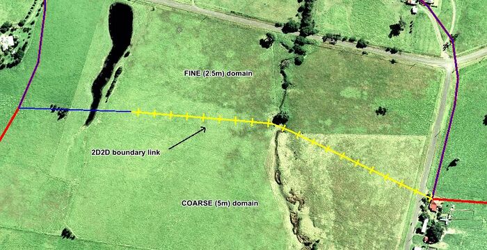
This tutorial updates the single domain 5m resolution model, incorporating a coarse resolution domain (5m) in the upstream half of the study area and a fine resolution (2.5m) domain in the downstream area. Multiple 2D domain models such as this require separate code boundaries to define the extent of each domain. Follow the steps below:
- The code boundary already created for Tutorial M01 will be reused to define the COARSE domain extent, however we will rename it for clarity. Import the M01 code boundary file 2d_code_M01_002.mif from the Complete_Model\TUFLOW\model\mi folder. Save the file as 2d_code_M09_5m_001.mif in the working TUFLOW\model\mi folder.
- To define the FINE domain, import an empty 2d_code_empty.mif template file from the TUFLOW\model\mi\empty folder and save it as 2d_code_M09_2.5m_001.mif in the TUFLOW\model\mi folder.
- Add the 2d_code layer to the Map window and make it editable.
- Open the layer FINEdomain_boundary.tab in the Module_Data\Module_09 folder.
- Select the polygon in this layer, copy to the clipboard and paste into 2d_code_M09_2.5m_001.mif.
- Assign the Code attribute for the polygon a value of 1 (Code 1 means set the 2D cells within the polygon to active).
- Save the two new 2d_code layers and export in MID/MIF format.
2D Location Lines
It is important to specify an appropriate domain origin, orientation and dimension for the new FINE domain. These domain features do not need to be the same in both domains.
- For this tutorial, we will be using a location line method to define the domain origins and orientations. The location lines (2d_loc) have been provided for you in the Module_Data\Module_09 folder.
- The 2d_loc line for the 5m domain will use the 2d_loc_M09_5m_001.mif, and the 2d_loc line for the 5m domain will use the 2d_loc_M09_2.5m_001.mif.
- Copy these files to the working TUFLOW\model\mi folder.

2D2D Boundary Condition Line
Multiple 2D domain models use the 2d_bc “2D” link type as the boundary cells for transfering flow between the neighbouring domains.
- The 2D2D boundary condition line inputs (2d_bc) have been provided for you in the Module_Data\Module_09 folder.
- Both domains will use the same file: 2d_bc_M09_2D2D_001.mif.
- Copy these files to the working TUFLOW\model\mi folder.
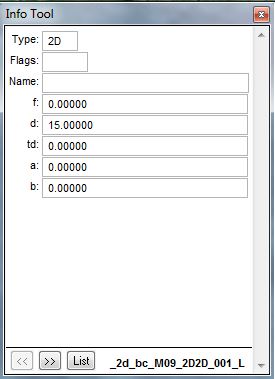
- Inspect the provided 2D2D boundary condition line and note the following inputs:
- Type: 2D
- d: 15
The Multiple Domain 2D/2D Boundary Condition Guidance section of the wiki provides guidance on appropriate values for 2D2D boundary condition attributes and line orientation advice for different magnitude flow conditions.


Model Inflow/Outflow Boundary Conditions
Multiple 2D domain modelling requires separate TUFLOW Boundary Condition Control files (.tbc) for each 2D domain. Each .tbc must contain unique boundary condition layers specific to its 2D domain (pits, SX lines, inflow/outflow boundaries, 1D/2D connections etc.) and also a common 2D2D boundary condition line input.
For the current tutorial:
- 2d_bc_M01_002.mif will need to be split into two separate layers that contain only the relevant objects within each domain. The upstream inflow will need to be associated with the coarse resolution domain .tbc. The downstream outflow will need to be associated with the fine resolution domain .tbc.
- 2d_sa_M01_002.mif is associated with the coarse resolution domain only.
- 2d_bc_M09_2D2D_001.mif is used by both domains.

Coarse Resolution Domain
- Import the M01 boundary file 2d_bc_M01_002.mif from the Complete_Model\TUFLOW\model\mi folder. Save the file as 2d_bc_M09_5m_001.mif in the working TUFLOW\model\mi folder.
- Open this newly created GIS layer and delete the downstream boundary condition polyline FC01_DS (this boundary condition will be used in the .tbc for the fine resolution domain).
- The M01 boundary file 2d_sa_M01_002.mif is already entirely located within the coarse domain. No changes are required for this input in this tutorial.
- Save the layers.
Fine Resolution Domain
- Import the M01 boundary file 2d_bc_M01_002.mif from the Complete_Model\TUFLOW\model\mi folder. Save the file as 2d_bc_M09_2.5m_001_L.mif in the working TUFLOW\model\mi folder.
- Open this newly created GIS layer and delete the upstream boundary condition polyline FC01 (this boundary condition is used in the .tbc for the coarse resolution domain).
- Save the layer.
Conclusion
The new 2d_code_M09_2.5m_001.mif polygon for the fine domain, the 2D2D boundary 2d_bc_M09_2D2D_001.mif, the boundary conditions 2d_bc_M09_5m_001.mif (inflow) and 2d_bc_M09_2.5m_001.mif (outflow) have been created.
Please return to Tutorial Module 9 for the next step to modify the simulation control files.