Tutorial Module09 Archive
- Open M01_5m_002.tcf in your text editor and save as M09_2D2D_001.tcf.
- Within the 'MODEL INPUTS' section, comment out (or delete) the "Geometry Control File" and "BC Control File" lines, using a comment character (! or #)
- ! Geometry Control File == ..\model\M01_5m_002.tgc
- ! BC Control File == ..\model\M01_5m_002.tbc
- Within the 'MODEL INPUTS' section, include the following commands:
- Start 2D Domain == COARSE
- Geometry Control File == ..\model\M09_2D2D_5m_001.tgc
- BC Control File == ..\model\M09_2D2D_5m_001.tbc
- Set IWL == 36.5
- Timestep == 1.5
- Geometry Control File == ..\model\M09_2D2D_5m_001.tgc
- End 2D Domain
- Start 2D Domain == FINE
- Geometry Control File == ..\model\M09_2D2D_2.5m_001.tgc
- BC Control File == ..\model\M09_2D2D_2.5m_001.tbc
- Set IWL == 36.5
- Timestep == 0.5
- Geometry Control File == ..\model\M09_2D2D_2.5m_001.tgc
- End 2D Domain
- Tip 1: Indenting commands within your Domain block makes your code more legible.
- Tip 2: The material and bc_dbase files can be read outside of the domain blocks as per a typical TUFLOW model.
- Start 2D Domain == COARSE
- Add the command Reveal 1D Nodes == ON
This command will include the location of 2D2D link boundary hidden 1D nodes within the nwk_N_check layer. refer for Multiple Domain 2D/2D Boundary Condition Guidance for more details about hidden 1D nodes. - Comment out (or delete) the 'INITIAL WATER LEVELS' section and "Timestep" line, using a comment character (! or #).
- ! Set IWL == 36.5
- ! Set IWL == 36.5
- ! Timestep == 1.5
- We will also update the log, output and check folder locations for this tutorial:
- Log Folder == log
- Output Folder == ..\results\M09\2d
- Write Check Files == ..\check\2d\
- Time Series Output Interval == 300
- Log Folder == log
- Adding the Time Series Output Interval command to the 'OUTPUT CONTROL AND FORMAT COMMANDS' section is required because of the Reveal 1D Nodes command. Excluding this output command will result in Error 0046 - 1D Output Interval not specified.
- Save the TCF file.
- Open M01_5m_002.tgc in your text editor. Save the file as M09_2D2D_5m_001.tgc.
- Within the '2D DOMAIN EXTENT AND RESOLUTION COMMANDS' section, comment out (or delete) the "Origin" and "Orientation" lines using a comment character (! or #)
- ! Origin == 292725, 6177615
- ! Origin == 292725, 6177615
- ! Orientation == 293580, 6177415
- Include the following command to replace the 'Origin' and 'Orientation' commands that were removed above:
- MapInfo Users
- Read GIS Location == mi\2d_loc_M09_5m_001.MIF
- QGIS or ArcGIS Users
- Read GIS Location == gis\2d_loc_M09_5m_001_L.shp
- MapInfo Users
- Update the grid size for the COARSE domain.
- Grid Size (X,Y) == 850, 575
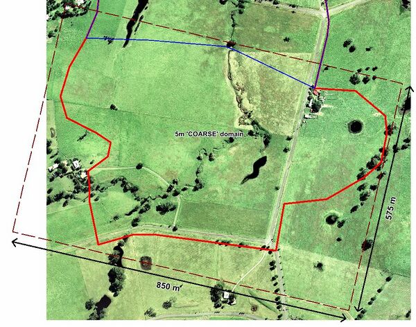
- Grid Size (X,Y) == 850, 575
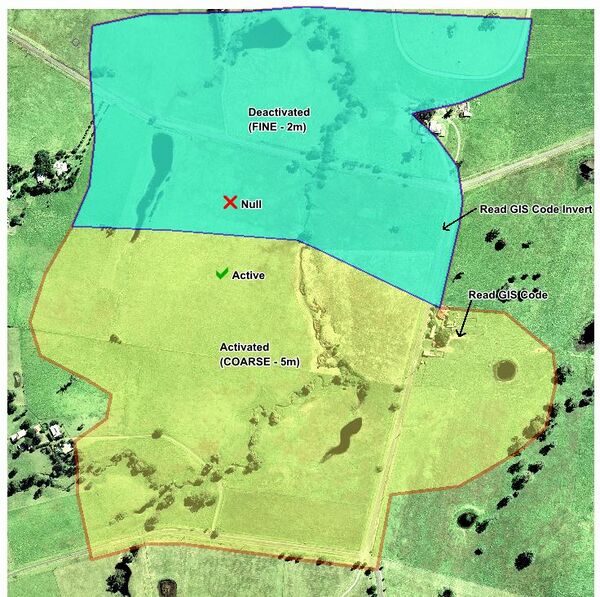
- Within the 'MODEL GRID COMMANDS' section, replace the Tutorial M01 referenced code boundary 2d_code_M01_002 with:
- MapInfo Users
- Read GIS Code == mi\2d_code_M09_5m_001.MIF
- Read GIS Code Invert == mi\2d_code_M09_2.5m_001.MIF
- QGIS or ArcGIS Users
- Read GIS Code == gis\2d_code_M09_5m_001_R.shp
- Read GIS Code Invert == gis\2d_code_M09_2.5m_001_R.shp
- MapInfo Users
- Save the file.
- Open M09_2D2D_5m_001.tgc in your text editor. Save the file as M09_2D2D_2.5m_001.tgc.
- Update the 2d location line reference. Replace 2d_loc_M09_5m_001_L with 2d_loc_M09_2.5m_001_L:
- MapInfo Users
- Read GIS Location == mi\2d_loc_M09_2.5m_001.MIF
- QGIS or ArcGIS Users
- Read GIS Location == gis\2d_loc_M09_2.5m_001_L.shp
- MapInfo Users
- Within the '2D DOMAIN EXTENT AND RESOLUTION COMMANDS' section, update the cell size value and domain grid dimensions:
- Cell Size == 2.5
- Grid Size (X,Y) == 725, 500
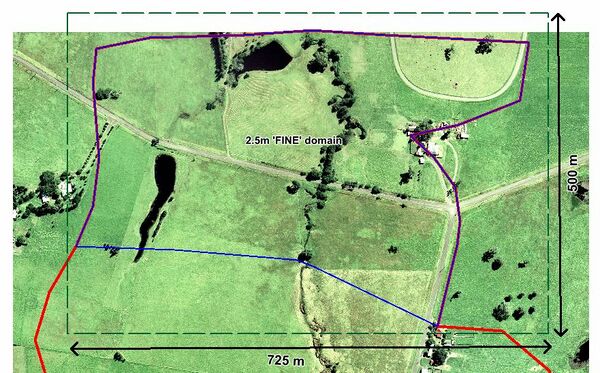
- Cell Size == 2.5
- Within the 'MODEL GRID COMMANDS' section, update the following commands:
- MapInfo Users
- Read GIS Code == mi\2d_code_M09_2.5m_001.MIF
- QGIS or ArcGIS Users
- Read GIS Code == gis\2d_code_M09_2.5m_001_R.shp
- MapInfo Users
- Existing elevation and material commands should remain unchanged in this example.
Note: Different datasets in each TGC file can be specified if desired, though the elevations along the 2D2D interface must match to achieve a stable exchange of flow between both domains. - Save the file.
- Open M01_5m_002.tbc in your text editor. Save the file as M09_2D2D_5m_001.tbc.
- Comment out (or delete) the "Read GIS BC" command, using a comment character (! or #)
- MapInfo Users
- ! Read GIS BC == mi\2d_bc_M01_002.mif
- QGIS or ArcGIS Users
- ! Read GIS BC == mi\2d_bc_M01_002
- MapInfo Users
- Do not comment out the Read GIS SA == 2d_sa_M01_002 inflow boundary command. The 2d_sa feature is situated in the COARSE domain and should remain.
- Include reference to the new file containing the upstream inflow location.
- MapInfo Users
- Read GIS BC == mi\2d_bc_M09_5m_001.MIF
- QGIS or ArcGIS Users
- Read GIS BC == gis\2d_bc_M09_5m_001_L.shp
- MapInfo Users
- Add reference to the 2D2D boundary line used to transfer flow between the COARSE and FINE domains.
- MapInfo Users
- Read GIS BC == mi\2d_bc_M09_2D2D_001.MIF
- QGIS or ArcGIS Users
- Read GIS BC == gis\2d_bc_M09_2D2D_001_L.shp
- MapInfo Users
- Save the file.
- Open M09_2D2D_5m_001.tbc in your text editor. Save the file as M09_2D2D_2.5m_001.tbc.
- As the 2d_sa_M01_002 inflow boundary is situated outside the FINE domain comment out or delete this layer from M09_2D2D_2.5m_001.tbc.
- Comment out the reference to the upstream inflow location (as it is not associated with the FINE resolution domain). Replace it with reference to the downstream outflow location:
- MapInfo Users
- ! Read GIS BC == mi\2d_bc_M09_5m_001_L.MIF
- Read GIS BC == mi\2d_bc_M09_2.5m_001.MIF
- QGIS or ArcGIS Users
- ! Read GIS BC == gis\2d_bc_M09_5m_001_L.shp
- Read GIS BC == gis\2d_bc_M09_2.5m_001_L.shp
- MapInfo Users
- Add reference to the 2D2D boundary line. This command is replicated in both the COARSE and FINE domain TBC files.
- MapInfo Users
- Read GIS BC == mi\2d_bc_M09_2D2D_001.MIF
- QGIS or ArcGIS Users
- Read GIS BC == gis\2d_bc_M09_2D2D_001_L.shp
- MapInfo Users
- Save the file. The TUFLOW simulation is now ready to run.
- Further multiple domain modelling advice can be found here. The modelling guidance page discusses appropriate hidden 1D node spacing, 2D2D boundary line orientation and storage multiplier options.
- There is also a webinar hosted by Bill Syme covering multiple 2D domains in more detail. You can find that presentation "Modelling with Difference Cell Sizes" here.
Introduction
In this module we will further develop the model from Module 01. Please complete Module 01 before attempting this tutorial, it is the starting point for the model updates documented below. We will be developing a multiple domain model that incorporates two different grid size within different portions of the model domain: a 2.5m 'FINE' grid and a 5m 'COARSE' grid. This module assumes that you have a good understanding of the different TUFLOW control files and are confident in navigating the TUFLOW file structure.
Note: Running a multiple domain model without a valid multiple domain licence (i.e. in Tutorial Mode) can only be achieved using TUFLOW Build 2016-03-AD or newer.
GIS Inputs
Download the Tutorial Model dataset relevant to your GIS environment (ArcGIS, MapInfo or QGIS) from the TUFLOW website. For this module you have been provided 2d location lines, a code polygon for the fine resolution domain, boundary condition lines datasets for the model inflow, outflow and the 2D2D boundary link. To import these datasets for this tutorial, please select your GIS package from the list below.

Modify Simulation Control Files
Having completed all the necessary GIS file updates, we now need to update our TUFLOW control files.
TUFLOW Control File (TCF)
Multiple domain models are defined in TUFLOW using 2D domain blocks within the TUFLOW Control File (TCF). Each domain block is defined using Start 2D Domain == <name> and End 2D Domain commands. Unique TUFLOW Geometry Control (TGC) file, Boundary Condition Control (TBC) file, initial water level, plot output and time step commands are defined within each domain block. All other commands (such as the boundary condition database, material file references, ESTRY control file and simulation time and map output commands) are defined outside the above mentioned 2D domain blocks.
We will create a new TCF based on Tutorial M01: M01_5m_002.tcf from your working TUFLOW\runs folder.:
TUFLOW Geometry Control (TGC)
TUFLOW Geometry Control (TGC) files are required for the COARSE and FINE domains.
Coarse Resolution Domain


Fine Resolution Domain

TUFLOW Boundary Control (TBC)
TUFLOW Boundary Control (TBC) files are required for the COARSE and FINE domains.
Coarse Resolution Domain
Fine Resolution Domain
Run Simulation and Review Results
Run M09_2D2D_001.tcf using your preferred method, as described in Module 1.
Note: release 2016-03-AD or newer is required to run this tutorial without a physical TUFLOW license.
Earlier TUFLOW releases will not run the tutorial model, and will generate the error shown below.

Review the model Map Output results in your preferred result viewing program (i.e. SMS, WaterRIDE, QGIS, Blue Kenue). Flood depth results are shown below. Notice the smooth transition in result across the 2D2D link.

Review Check Files
Review the model check files after the simulation is completed. The following sections outline how the check files can be used to review each of the key changes we have made to the model.
1D Nodes
Flow is transferred between both domains via a series of hidden 1D nodes. The hidden 1D nodes act as storage for the passing of mass from one 2D domain to the other. Strange flow patterns can occur if the water profile is not close to linear between vertices, which can in turn lead to instabilities. As such, appropriate resolution of the hidden 1D nodes is an important feature of multiple 2D domain models. The location of hidden 1D nodes can be viewed in the M09_2D2D_001_nwk_N_check file.

Advice on appropriate hidden 1D node spacing is available here. More information concerning the nwk_N_check check file can also be found here.
Multiple Domains
The grd_check file is useful for confirming whether overlapping domains have been correctly deactivated. Import M09_2D2D_001_grd_check. Refer to Item 1 in Multiple Domain 2D/2D Boundary Condition Guidance.
The 2d_to_2d_check file is useful to review the location of the 2D2D boundary condition cells. Import M09_2D2D_2.5m5m_001_2d_to_2d_check. The coloured grid cells highlight the boundary cells that are selected for each hidden 1D node that was previously specified using the "d" attribute. More information concerning the 2d_to_2d check file can be found here.


Additional Information
Multiple 2D Domain Modelling Using HPC
Refer to the current Tutorial M07 for instructions on how to run Quadtree nesting with HPC.