Tute M14 QGIS 2d bc pump Archive
Introduction
This page details the method for using QGIS to create the additional required GIS boundary layer. The process of editing and saving GIS layers using QGIS is the same as that described in Module 1. If you are not familiar with how to do this, please review the detailed method described for Module 1.
Method
We need to create the 2d_bc layer to contain the pump, which takes the flow from a 2D cell and transfers the water to a separate 2d cell.
- In QGIS open the DEM layer used in previous modules.
- Open the Pump.shp layer provided in the Module_Data\Module_14\QGIS\ folder. In this module a pump will be added along the creek together with a connecting line to the shallow reservoir located to the west.
- Open the 2d_bc_empty_P.shp template file from the TUFLOW\Model\gis\empty\ folder. Save this template layer as 2d_bc_M14_pump_001_P.shp in the TUFLOW\Model\gis folder.
- Check the 'add saved file to map' box when saving the new layer or alternatively load the new layer to the current view. Toggle editing for the new layer. The template file may now be closed.
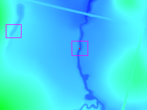
- Using the Select Single Feature tool, select the pump object contained in the Pump layer. Copy the pump object using Edit >> Copy Feature or Ctrl+C, select the 2d_bc_M14_pump_P layer in the layer control, toggle editing on and then select Edit >> Paste or Ctrl+V. The location of the pump is shown below, with the reservoir to the west.
- The pump requires only two attributes to be entered. Right-click on the 2d_bc_M14_pump_001_P layer and select 'Open Attribute Table'. The attribute table shows all attributes currently associated with the pump object. Double-click on the Type attribute and change the type to SH. Using the same method change the object Name to pump. For a description of each of these attributes, refer to the TUFLOW Manual. The Type attribute tells TUFLOW what type of 2d boundary is being created, while the Name provides a link to the relevant boundary condition data to be read from the boundary condition database.
- We now need to specify where we want the flow removed from the creek to be transferred to. To do this a connection feature is required.
- Open the 2d_bc_empty_L.shp template file from the TUFLOW\Model\gis\empty\ folder. Save this template layer as 2d_bc_M14_pump_001_L.shp in the TUFLOW\Model\gis folder.
- Check the 'add saved file to map' box when saving the new layer or alternatively load the new layer to the current view. Toggle editing for the new layer. The template file may now be closed.
- Before we begin modifying the new 2d_bc layer we need to enable snapping to the 2d_bc pump object. Enable snapping for this layer in the Settings >> Snapping Options... menu. Select the check box next to the 2d_bc_M14_pump_001_P layer. Set the tolerance to 5 map units (5 metres) and select 'Apply'.
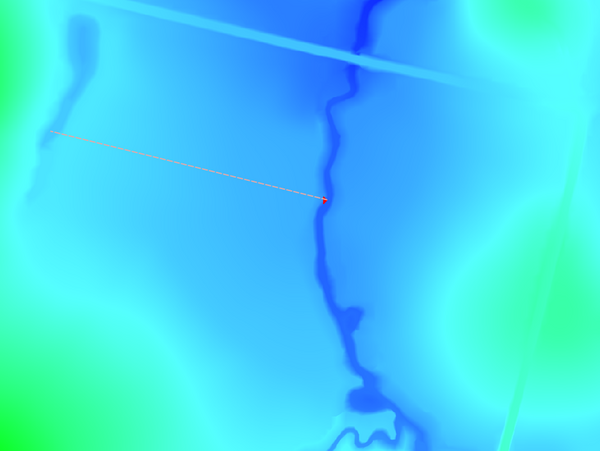
- Select the 2d_bc_M14_pump_001_L layer and toggle editing on. Using the Add Feature tool, digitise a line object, snapping to the pump object and ending at the location where the flow is to be transferred to, as shown below. Right-click on the map window to complete the line.
- With the line complete, an attributes window will be displayed. Enter the line Type as SC. Make all other attributes blank by removing any null entries.
- Save edits to the 2d_bc_M14_pump_001_L layer to finish.


Conclusion
The 2d_bc_M14_pump_001_P and 2d_bc_M14_pump_001_L layers are ready for input to the TUFLOW model. The next step is to link the pump with a boundary condition entry in the boundary condition database (bc_dbase).
When ready you may return to Module 14 Modify Simulation Control Files and Boundary Condition Database.