1D Culverts: Difference between revisions
Rohan.king (talk | contribs) |
|||
| (55 intermediate revisions by 6 users not shown) | |||
| Line 1: | Line 1: | ||
<font size = 18>Page Under Construction</font> |
|||
| ⚫ | |||
| ⚫ | |||
| ⚫ | |||
=Introduction= |
=Introduction= |
||
A culvert is a structure that allows water to flow under a road, embankment, railway or other similar obstruction from one side to the other. Culverts or pipe channels can be either rectangular, circular (pipe) or irregular in shape and can vary in size depending on the flow and design requirements. |
|||
<br> |
<br> |
||
*Advice on SX connections & number of cells to connect to 2D domain – implications |
|||
*Flow regimes – theory behind each. |
|||
*How to check for the flow regime – link to check file |
|||
*How do we sub divide logic rules (operational culverts)* |
|||
*Losses – fixed, Englehund, automatic manholes etc. |
|||
*Provide some justification on the ‘default’ height/width, entry/exit losses. |
|||
=1D-2D Connections= |
=1D-2D Connections= |
||
Connection of a 1D drainage network to the 2D domain typical occurs using one of the following features: <br> |
|||
*1D inlet pits (more details can be found [[1D_Pits | here]]). |
|||
*Manually assigned 2D SX connections |
|||
Information on how to create a 1D-2D connection in a GIS package are explained within <u>[[Tutorial_M03 | TUFLOW Tutorial Module 3]]</u>. |
|||
===SX Connection Hints=== |
|||
To limit the doubling up of expansion and contraction losses on a culvert (as 1D nwke culverts will already contain height, width, entry and exit coefficients) the 2D flow into and out of a culvert should be as representative of the culvert dimensions. You can achieve this by selecting the number of 2D cells that best matches the width/diameter of your particular culvert. The example below shows a 4m culvert that has used an SX line to select 2 x 2m grid cells to discharge to. Remember that the selection of a particular cell, when using a polyline, requires the polyline intersect the cell cross-hair - refer to the <u>[https://docs.tuflow.com/classic-hpc/manual/latest/ TUFLOW Manual]</u>. <br> |
|||
[[File:Culvert_SX_connection_1.JPG|border|500px]] |
|||
| ⚫ | |||
| ⚫ | |||
Standard SX connections on the 1D network to the 2D domain where the terrain surface (cell elevations) is greater than the 1D node level will result in an <font color="red"><tt>Error 2050</tt></font><tt>.</tt> Details about this error can be found [[TUFLOW_Message_2050 | here]].<br> |
|||
<div><ul> |
|||
<li style="display: inline-block;"> [[File:SX_connection_1.JPG|thumb|none|800px|2D SX connection]] </li> |
|||
<li style="display: inline-block;"> [[File:SX_connection_1LS.JPG|thumb|none|700px|2D SX connection - Section view]] </li> |
|||
</ul></div> |
|||
| ⚫ | |||
Including a "Z" flag will only lower the selected 1D-2D cell. The level of water within the hole will need to increase above the surrounding surface before it will flow into the 2D domain. Using the "Z" can lead to instability issues so it is important to ensure the DTM modification is appropriate in your model. Details about this warning can be found [[TUFLOW_Message_2118 | here]].<br> |
|||
<div><ul> |
|||
<li style="display: inline-block;"> [[File:SX_connection_2.JPG|thumb|none|800px|2D SX connection with "Z" flag]] </li> |
|||
<li style="display: inline-block;"> [[File:SX_connection_2LS.JPG|thumb|none|700px|2D SX connection with "Z" flag - Section view]] </li> |
|||
</ul></div> |
|||
<br> |
|||
Including a Zline or Zshape that modifies the surrounding topography removes any warning or error, in this particular case the Zline also creates a smooth transition for water to flow from the culvert. No need for a "Z" is required. |
|||
<div><ul> |
|||
<li style="display: inline-block;"> [[File:SX_connection_3.JPG|thumb|none|800px|2D SX connection with Zline]] </li> |
|||
<li style="display: inline-block;"> [[File:SX_connection_3LS.JPG|thumb|none|700px|2D SX connection with Zline - Section view]] </li> |
|||
</ul></div> |
|||
=Flow Regimes= |
=Flow Regimes= |
||
The flow regime through a culvert are divided into the following types. Checking this information for any 1D culvert can be inspected from the _TSF.mif/_TSF_P.shp that outputs the regime at each output interval. <br> |
The flow regime through a culvert are divided into the following types. Checking this information for any 1D culvert can be inspected from the _TSF.mif/_TSF_P.shp that outputs the regime at each output interval. <br> |
||
{| |
{| class="wikitable" |
||
! style="background-color:#005581; font-weight:bold; color:white;"| Regime |
! style="background-color:#005581; font-weight:bold; color:white;"| Regime |
||
| Line 42: | Line 61: | ||
| K|| Unsubmerged entrance and submerged exit. Critical flow at entrance. Upstream controlled with the flow control at the inlet. Hydraulic jump along culvert |
| K|| Unsubmerged entrance and submerged exit. Critical flow at entrance. Upstream controlled with the flow control at the inlet. Hydraulic jump along culvert |
||
|- |
|- |
||
| L|| Submerged entrance and exit. Orifice flow at entrance. Upstream controlled with the flow control at the inlet. Hydraulic jump along culvert. |
| L|| Submerged entrance and exit. Orifice flow at entrance. Upstream controlled with the flow control at the inlet. Hydraulic jump along culvert. |
||
|} |
|} |
||
| ⚫ | |||
<br><br><br><br><br> |
|||
'''Example of the _TSF results in GIS:'''<br> |
'''Example of the _TSF results in GIS:'''<br> |
||
[[File:TSF_result_file.JPG|border|600px]] |
[[File:TSF_result_file.JPG|border|600px]] |
||
| Line 52: | Line 69: | ||
The GIS results for the _TSF layer show the flow regime that was recorded at each output interval. |
The GIS results for the _TSF layer show the flow regime that was recorded at each output interval. |
||
=Modelling Bend Losses= |
|||
=Operational Control= |
|||
Where bends occur within one culverted length, additional losses can be applied using the form_loss attribute of the 1d_nwk layer. This applies the energy loss appropriately for a 'minor' loss using K*V<sup>2</sup>/2g. Bend loss coefficients (K) are found in many standard hydraulic references, e.g.: |
|||
| ⚫ | |||
| ⚫ | |||
:*<u>[https://www.business.qld.gov.au/industries/mining-energy-water/water/industry-infrastructure/supply-planning/urban-stormwater-drainage Queensland Urban Drainage Manual]</u> |
|||
| ⚫ | |||
:*<u>[https://www.ciria.org/CIRIA/Item_Detail.aspx?WebsiteKey=3f18c87a-d62b-4eca-8ef4-9b09309c1c91&iProductCode=C689F&Category=FREEPUBS&OrderLineId=71a52fd5-34ac-4bd9-b219-e1c97a45e059 Culvert Design and Operation Guide (C689F) by CIRIA]</u> |
|||
:*<u>[https://www.fhwa.dot.gov/engineering/hydraulics/pubs/12026/hif12026.pdf Hydraulic Design of Highway Culverts by the U.S. FHWA]</u> |
|||
| ⚫ | |||
| ⚫ | The table below highlights some of the commonly used check files when reviewing 1D culverts. Although this list may not be all the check file you could use to review 1D culverts it is certainly a good starting point. The full list of TUFLOW check files can be found <u>[[TUFLOW_Check_Files | here]]</u>. <br> |
||
| ⚫ | |||
! style="background-color:#005581; font-weight:bold; color:white;"| Filename prefix / suffix |
! style="background-color:#005581; font-weight:bold; color:white;"| Filename prefix / suffix |
||
! style="background-color:#005581; font-weight:bold; color:white;" width=75%| Brief Description |
|||
|- |
|- |
||
| [[Check_Files_1d_inverts | _inverts_check.mif<br>_inverts_check_P.shp]] |
| [[Check_Files_1d_inverts | _inverts_check.mif<br>_inverts_check_P.shp]] |
||
|- |
|- |
||
| [[Check_Files_1d_IWL | _iwl_check.mif<br>_iwl_check_P.shp]] |
| [[Check_Files_1d_IWL | _iwl_check.mif<br>_iwl_check_P.shp]] |
||
|- |
|- |
||
| [[Check_Files_1d_nwk_C | _nwk_C_check.mif<br>_nwk_C_check_L.shp]] |
| [[Check_Files_1d_nwk_C | _nwk_C_check.mif<br>_nwk_C_check_L.shp]] |
||
The layers lines are coloured based on the channel type (available for the .mid/.mif format only).<br> |
|||
Any generated pit channels are shown as a small channel flowing from north to south into the pit node. The upstream pit channel node that is generated is also shown. The length of the pit channel is controlled by <tt>Pit Channel Offset == </tt> command. |
|||
|- |
|- |
||
| [[Check_Files_1d_nwk_N | _nwk_N_check.mif<br>_nwk_N_check_P.shp]] |
| [[Check_Files_1d_nwk_N | _nwk_N_check.mif<br>_nwk_N_check_P.shp]] |
||
The node symbology is displayed as a red circle for nodes connected to two or more channels, a larger magenta circle for nodes connected to one channel and a large yellow square for nodes not connected to a channel (available for the .mid/.mif format only). '''This is very useful for checking for channel ends or nodes that are not snapped.'''<br> |
|||
The top and bottom elevations of the NA table at nodes is now shown using the Upstream_Invert and Downstream_Invert attributes. |
|||
|} |
|} |
||
| ⚫ | |||
<br> |
<br> |
||
<br> |
<br> |
||
Any further questions please email TUFLOW support: [mailto:support@tuflow.com support@tuflow.com] |
Any further questions please email TUFLOW support: [mailto:support@tuflow.com?Subject=TUFLOW%201D%20culverts%20help support@tuflow.com] |
||
<br><br> |
|||
{{Tips Navigation |
|||
|uplink=[[ TUFLOW 1D Channels and Hydraulic Structures | Back to 1D Channels and Hydraulic Structures]] |
|||
}} |
|||
Latest revision as of 12:32, 2 March 2026
Introduction
A culvert is a structure that allows water to flow under a road, embankment, railway or other similar obstruction from one side to the other. Culverts or pipe channels can be either rectangular, circular (pipe) or irregular in shape and can vary in size depending on the flow and design requirements.
1D-2D Connections
Connection of a 1D drainage network to the 2D domain typical occurs using one of the following features:
- 1D inlet pits (more details can be found here).
- Manually assigned 2D SX connections
Information on how to create a 1D-2D connection in a GIS package are explained within TUFLOW Tutorial Module 3.
SX Connection Hints
To limit the doubling up of expansion and contraction losses on a culvert (as 1D nwke culverts will already contain height, width, entry and exit coefficients) the 2D flow into and out of a culvert should be as representative of the culvert dimensions. You can achieve this by selecting the number of 2D cells that best matches the width/diameter of your particular culvert. The example below shows a 4m culvert that has used an SX line to select 2 x 2m grid cells to discharge to. Remember that the selection of a particular cell, when using a polyline, requires the polyline intersect the cell cross-hair - refer to the TUFLOW Manual.

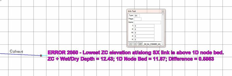
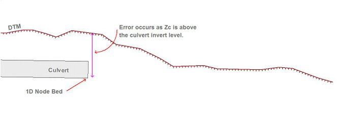
Standard SX connections on the 1D network to the 2D domain where the terrain surface (cell elevations) is greater than the 1D node level will result in an Error 2050. Details about this error can be found here.
-
2D SX connection -
2D SX connection - Section view


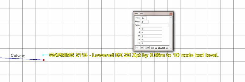
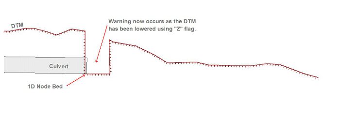
Including a "Z" flag will only lower the selected 1D-2D cell. The level of water within the hole will need to increase above the surrounding surface before it will flow into the 2D domain. Using the "Z" can lead to instability issues so it is important to ensure the DTM modification is appropriate in your model. Details about this warning can be found here.
-
2D SX connection with "Z" flag -
2D SX connection with "Z" flag - Section view


Including a Zline or Zshape that modifies the surrounding topography removes any warning or error, in this particular case the Zline also creates a smooth transition for water to flow from the culvert. No need for a "Z" is required.
-
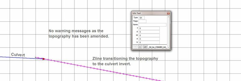
2D SX connection with Zline -
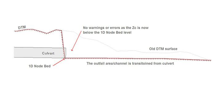
2D SX connection with Zline - Section view


Flow Regimes
The flow regime through a culvert are divided into the following types. Checking this information for any 1D culvert can be inspected from the _TSF.mif/_TSF_P.shp that outputs the regime at each output interval.
| Regime | Description |
|---|---|
| A | Unsubmerged entrance and exit. Critical flow at entrance. Upstream controlled with the flow control at the inlet. |
| B | Submerged entrance and unsubmerged exit. Orifice flow at entrance. Upstream controlled with the flow control at the inlet. |
| C | Unsubmerged entrance and exit. Critical flow at exit. Upstream controlled with the flow control at the culvert outlet. |
| D | Unsubmerged entrance and exit. Sub-critical flow at exit. Downstream controlled. |
| E | Submerged entrance and unsubmerged exit. Full pipe flow. Upstream controlled with the flow control at the culvert outlet. |
| F | Submerged entrance and exit. Full pipe flow. Downstream controlled. |
| G | No flow. Dry or flap-gate active. |
| H | Submerged entrance and unsubmerged exit. Adverse slope. Downstream controlled. |
| J | Unsubmerged entrance and exit. Adverse slope. Downstream controlled. |
| K | Unsubmerged entrance and submerged exit. Critical flow at entrance. Upstream controlled with the flow control at the inlet. Hydraulic jump along culvert |
| L | Submerged entrance and exit. Orifice flow at entrance. Upstream controlled with the flow control at the inlet. Hydraulic jump along culvert. |
Example of the _TSF results in GIS:

The GIS results for the _TSF layer show the flow regime that was recorded at each output interval.
Modelling Bend Losses
Where bends occur within one culverted length, additional losses can be applied using the form_loss attribute of the 1d_nwk layer. This applies the energy loss appropriately for a 'minor' loss using K*V2/2g. Bend loss coefficients (K) are found in many standard hydraulic references, e.g.:
Typical Check Files
The table below highlights some of the commonly used check files when reviewing 1D culverts. Although this list may not be all the check file you could use to review 1D culverts it is certainly a good starting point. The full list of TUFLOW check files can be found here.
| Filename prefix / suffix |
|---|
| _inverts_check.mif _inverts_check_P.shp |
| _iwl_check.mif _iwl_check_P.shp |
| _nwk_C_check.mif _nwk_C_check_L.shp |
| _nwk_N_check.mif _nwk_N_check_P.shp |
Any further questions please email TUFLOW support: support@tuflow.com
| Up |
|---|