Flood Modeller Tutorial Module01: Difference between revisions
Andrew.Sims (talk | contribs) |
Steph.dufour (talk | contribs) No edit summary |
||
| Line 2: | Line 2: | ||
In this module we will link an existing 2D TUFLOW domain to an existing Flood Modeller 1D model. The 2D TUFLOW domain will represent the floodplain in the study area, and the 1D Flood Modeller model will represent the watercourse and all online structures. <br> |
In this module we will link an existing 2D TUFLOW domain to an existing Flood Modeller 1D model. The 2D TUFLOW domain will represent the floodplain in the study area, and the 1D Flood Modeller model will represent the watercourse and all online structures. <br> |
||
1D-2D linked models are able to utilise the individual benefits of 1D and 2D solution schemes. In this example, the 1D Flood Modeller scheme is used to represent the watercourses where the flow is essentially one-directional. A 2D scheme is suited to the representation of floodplains where |
1D-2D linked models are able to utilise the individual benefits of 1D and 2D solution schemes. In this example, the 1D Flood Modeller scheme is used to represent the watercourses where the flow is essentially one-directional. A 2D scheme is suited to the representation of floodplains where more complex flow patterns may occur. <br> |
||
<br> |
<br> |
||
As [[Tutorial_Module01#Reviewing_Model_Performance | discussed in Module 1]], the main |
As [[Tutorial_Module01#Reviewing_Model_Performance | discussed in Module 1 of the TUFLOW Tutorial Model]], the main watercourse channel is not very well represented using the 5m 2D cell size. In parts, the watercourse is only 5-10m wide and the 5m cell size could be considered too coarse to accurately represent the watercourse topography.<br> |
||
[[file:Poor_2d_rep.png|400px]]<br> |
[[file:Poor_2d_rep.png|400px]]<br> |
||
Using a cell size that is coarse relative to the width of the |
Using a cell size that is coarse relative to the width of the watercourse channel may reduce the accuracy of the conveyance in the channel. There are two options for improving the representation of the creek channel:<br> |
||
* decrease the width of the 2D cells; and/or |
* decrease the width of the 2D cells; and/or |
||
* model the channel as a 1D network, dynamically linked to the 2D domain (the floodplain). |
* model the channel as a 1D network, dynamically linked to the 2D domain (the floodplain). |
||
In the [[Tutorial_Module01#Advanced_.28Optional.29 | optional section of |
In the [[Tutorial_Module01#Advanced_.28Optional.29 | optional section of Module 1 of the TUFLOW Tutorial Model]], we looked at reducing the cell size to get a better representation of the channel. In this module we will adopt the second approach of modelling the creek as 1D elements using Flood Modeller.<br> |
||
<br> |
<br> |
||
TUFLOW may be dynamically linked to 1D networks using the hydrodynamic solutions of ESTRY (TUFLOW 1D), Flood Modeller (previously ISIS), XP-SWMM and 12D Solutions’ Dynamic Drainage.<br> |
TUFLOW may be dynamically linked to 1D networks using the hydrodynamic solutions of ESTRY (TUFLOW 1D), Flood Modeller (previously ISIS), XP-SWMM and 12D Solutions’ Dynamic Drainage.<br> |
||
Setting up a 1D/2D model where the 1D channel cuts through the 2D domain is probably the most time-consuming type of a model to setup. However, the reduction in simulation time can be beneficial and make this a good approach. For this module, the complete Flood Modeller 1D model has been provided, |
Setting up a 1D/2D model where the 1D channel cuts through the 2D domain is probably the most time-consuming type of a model to setup. However, the reduction in simulation time can be beneficial and make this a good approach. For this module, the complete Flood Modeller 1D model has been provided, to allow for progressing through the module in a relatively short period of time.<br> |
||
=Existing Model Data= |
=Existing Model Data= |
||
This tutorial builds upon the 2D TUFLOW domain that was constructed as part of [[Tutorial Module01|Module 1]] and [[Tutorial Module02|Module 2]] of the TUFLOW Tutorial |
This tutorial builds upon the 2D TUFLOW domain that was constructed as part of [[Tutorial Module01|Module 1]] and [[Tutorial Module02|Module 2]] of the TUFLOW Tutorial Model.<br> |
||
The model developed in these tutorial modules already contains some culverts modelled as 1D elements. The culverts are modelled in ESTRY, TUFLOW's internal 1D engine. One of these culverts will be kept in ESTRY and the other will be |
The model developed in these tutorial modules already contains some culverts modelled as 1D elements. The culverts are modelled in ESTRY, TUFLOW's internal 1D engine. One of these culverts will be kept in ESTRY and the other will be added to the Flood Modeller model.<br> |
||
The 2D boundary conditions (upstream inflows and downstream stage-discharge boundary) will be removed from the model. These will instead be represented in Flood Modeller as it is a more typical schematisation for a 1D/2D linked model.<br> |
The 2D boundary conditions (upstream inflows and downstream stage-discharge boundary) will be removed from the model. These will instead be represented in Flood Modeller as it is a more typical schematisation for a 1D/2D linked model.<br> |
||
The existing TUFLOW model consists of: |
The existing TUFLOW model consists of: |
||
| Line 24: | Line 24: | ||
*1D/2D boundary links to connect the 1D ESTRY culverts to the 2D TUFLOW domain. |
*1D/2D boundary links to connect the 1D ESTRY culverts to the 2D TUFLOW domain. |
||
For further information on these elements, please refer to [[Tutorial Module01|Module 1]] and [[Tutorial Module02|Module 2]] of the TUFLOW Tutorial Model. |
|||
==Flood Modeller== |
==Flood Modeller== |
||
| Line 36: | Line 36: | ||
For this tutorial, the floodplain of the study area will be modelled entirely in TUFLOW. |
For this tutorial, the floodplain of the study area will be modelled entirely in TUFLOW. |
||
The cross-sections in the Flood Modeller 1D model have been trimmed to the top of bank to ensure there is no double-counting of storage within the floodplain. |
The cross-sections in the Flood Modeller 1D model have been trimmed to the top of bank to ensure there is no double-counting of storage within the floodplain. |
||
Upstream and downstream boundary data is contained separately within the IED files. These will be referenced and linked to the Flood Modeller 1D model via the IEF |
Upstream and downstream boundary data is contained separately within the IED files. These will be referenced and linked to the Flood Modeller 1D model via the IEF simulation file. |
||
=GIS and Model Inputs= |
=GIS and Model Inputs= |
||
| Line 167: | Line 167: | ||
The DAT and IED files are complete and will not require any modification to link to TUFLOW.<br> |
The DAT and IED files are complete and will not require any modification to link to TUFLOW.<br> |
||
However, we will alter the IEF to create the link. The IEF alterations can be done either in a text editor of your choice or using the Flood Modeller Interface.<br> |
However, we will alter the IEF to create the link. The IEF alterations can be done either in a text editor of your choice or using the Flood Modeller Interface.<br> |
||
The instructions below have been written for Flood Modeller Interface |
The instructions below have been written for the Flood Modeller Interface version 4.2.<br> |
||
==IEF File== |
==IEF File== |
||
| Line 180: | Line 180: | ||
*Use Initial Conditions from: Network File (.dat) |
*Use Initial Conditions from: Network File (.dat) |
||
*Results File: the full path to \FMT_Tutorial\FMT_M01\Flood_Modeller\RES\FMT_M01_001 |
*Results File: the full path to \FMT_Tutorial\FMT_M01\Flood_Modeller\RES\FMT_M01_001 |
||
<li>To the right of the Event Data box, click Add and select the ''' |
<li>To the right of the Event Data box, click Add and select the '''FMT_Inflows.IED''' file in the '''\FMT_Tutorial\FMT_M01\Flood_Modeller\IED''' folder.</li> |
||
[[file:FMT Simulation files.JPG|500px]] |
[[file:FMT Simulation files.JPG|500px]] |
||
<li>On the 'Times' tab, we will replace the simulation time parameters that were removed from TUFLOW. Enter the following parameters:</li> |
<li>On the 'Times' tab, we will replace the simulation time parameters that were removed from TUFLOW. Enter the following parameters:</li> |
||
Revision as of 23:38, 3 January 2017
Introduction
In this module we will link an existing 2D TUFLOW domain to an existing Flood Modeller 1D model. The 2D TUFLOW domain will represent the floodplain in the study area, and the 1D Flood Modeller model will represent the watercourse and all online structures.
1D-2D linked models are able to utilise the individual benefits of 1D and 2D solution schemes. In this example, the 1D Flood Modeller scheme is used to represent the watercourses where the flow is essentially one-directional. A 2D scheme is suited to the representation of floodplains where more complex flow patterns may occur.
As discussed in Module 1 of the TUFLOW Tutorial Model, the main watercourse channel is not very well represented using the 5m 2D cell size. In parts, the watercourse is only 5-10m wide and the 5m cell size could be considered too coarse to accurately represent the watercourse topography.

Using a cell size that is coarse relative to the width of the watercourse channel may reduce the accuracy of the conveyance in the channel. There are two options for improving the representation of the creek channel:
- decrease the width of the 2D cells; and/or
- model the channel as a 1D network, dynamically linked to the 2D domain (the floodplain).
In the optional section of Module 1 of the TUFLOW Tutorial Model, we looked at reducing the cell size to get a better representation of the channel. In this module we will adopt the second approach of modelling the creek as 1D elements using Flood Modeller.
TUFLOW may be dynamically linked to 1D networks using the hydrodynamic solutions of ESTRY (TUFLOW 1D), Flood Modeller (previously ISIS), XP-SWMM and 12D Solutions’ Dynamic Drainage.
Setting up a 1D/2D model where the 1D channel cuts through the 2D domain is probably the most time-consuming type of a model to setup. However, the reduction in simulation time can be beneficial and make this a good approach. For this module, the complete Flood Modeller 1D model has been provided, to allow for progressing through the module in a relatively short period of time.
Existing Model Data
This tutorial builds upon the 2D TUFLOW domain that was constructed as part of Module 1 and Module 2 of the TUFLOW Tutorial Model.
The model developed in these tutorial modules already contains some culverts modelled as 1D elements. The culverts are modelled in ESTRY, TUFLOW's internal 1D engine. One of these culverts will be kept in ESTRY and the other will be added to the Flood Modeller model.
The 2D boundary conditions (upstream inflows and downstream stage-discharge boundary) will be removed from the model. These will instead be represented in Flood Modeller as it is a more typical schematisation for a 1D/2D linked model.
The existing TUFLOW model consists of:
- Definition of Active/In-Active Areas
- Definition of Land Use
- 1D ESTRY culverts
- 1D/2D boundary links to connect the 1D ESTRY culverts to the 2D TUFLOW domain.
For further information on these elements, please refer to Module 1 and Module 2 of the TUFLOW Tutorial Model.
Flood Modeller
A complete Flood Modeller 1D model of the watercourse has been provided for the purposes of this tutorial.
The model data has been arranged in the following folder structure:
- DAT: Contains the Flood Modeller 1D network file.
- IED: Contains event data of the model.
- IEF: A blank folder in which to store Flood Modeller Event Files used to simulate the model.
- RES: A blank folder in which to write the Flood Modeller result files.
For further information on each file type, please refer to the Flood Modeller User Manual.
For this tutorial, the floodplain of the study area will be modelled entirely in TUFLOW.
The cross-sections in the Flood Modeller 1D model have been trimmed to the top of bank to ensure there is no double-counting of storage within the floodplain.
Upstream and downstream boundary data is contained separately within the IED files. These will be referenced and linked to the Flood Modeller 1D model via the IEF simulation file.
GIS and Model Inputs
The steps necessary to modify each of the GIS inputs are demonstrated in MapInfo, ArcGIS and QGIS. At each stage please select your GIS package to view relevant instructions.
Define the External 1D Networks
This part of the module creates the GIS layers that specify the location of the Flood Modeller nodes that are to be connected to the 2D domain. Follow the instructions below for your preferred GIS package.
Define the 1D/2D Boundary Links
This part of the module creates the 1D/2D boundaries to link the Flood Modeller 1D component to the TUFLOW 2D domain. Follow the instructions below for your preferred GIS package.
Define Bank Elevations
This part of the module defines the bank elevations of the watercourse which are the elevations of the 1D/2D boundary links created in the previous section. Follow the instructions below for your preferred GIS package.
Deactivate 2D cells
This part of the module describes the steps to deactivate the 2D cells where the 1D model is replacing the 2D solution. Follow the instructions below for your preferred GIS package.
Modify Simulation Control Files
Now that we have made all of the necessary changes to the GIS layers, we need to update the TUFLOW control files and Flood Modeller Simulation Files to create a linked model.
TUFLOW Control Files
TUFLOW Geometry Control File
We will first update the TUFLOW Geometry Control (TGC) file.
The following changes have been changes made to the geometry:
- We have turned off the cells in the channel (as these are now modelled in Flood Modeller)
- We have added the bank lines as topography amendments.
- In the \FMT_Tutorial\FMT_M01\TUFLOW\model folder, save a copy of M01_5m_002.tgc as FMT_M01_001.tgc.
- Open FMT_M01_001.tgc
Mapinfo
Add an extra line after Read GIS Code ==..\model\mi\2d_code_FMT_M01_001.MIF - Read GIS Code BC == mi\2d_bc_FMT_M01_HX_001.MIF ! Deactivates the cells where the creek channel has been modelled in 1D
- Read GIS Code BC == gis\2d_bc_FMT_M01_HX_001_R.shp ! Deactivates the cells where the creek channel has been modelled in 1D
- Topography amendments should be added in a new section at the bottom of the file. These are: Mapinfo
- Read GIS Z HX Line MAX == mi\2d_bc_FMT_M01_HX_001.MIF | mi\2d_bc_FMT_M01_HX_001_P.MIF ! Defines the bank crest levels (1D/2D boundary cell elevations). The 'MAX' option prevents any zpt elevations from being lowered
- Read GIS Z HX Line MAX == gis\2d_bc_FMT_M01_HX_001_L.shp | gis\2d_bc_FMT_M01_HX_001_P.shp ! Defines the bank crest levels (1D/2D boundary cell elevations). The 'MAX' option prevents any zpt elevations from being lowered
- Save the file. The geometry file is now ready to be used.
Add an extra line after Read GIS Code ==..\model\gis\2d_code_FMT_M01_001_R.shp
TUFLOW Boundary Condition Control File
We will now update the TUFLOW Boundary Condition control file (tbc) to reference the model boundary files created in previous steps.
- Open M02_5m_001.tbc and save a copy as FMT_M01_001.tbc.
- Remove the boundary linking to the TUFLOW inflows by:
Mapinfo- Put an exclamation mark before the line reading:
- Read GIS BC == mi\2d_bc_M01_002.MIF
- Put an exclamation mark before the line reading:
- Read GIS BC == gis\2d_bc_M01_002_L.SHP
- Put an exclamation mark before the line reading:
- Add the Boundaries for the culverts and to link to Flood Modeller: Mapinfo
- Read GIS BC == mi\2d_bc_M04_culverts_001.MIF ! This command reads in SX boundaries linking the 1D ESTRY culverts to the 2D domain
- Read GIS BC == mi\2d_bc_FMT_M01_HX_001.MIF ! This command reads in HX boundaries linking the 1D Flood Modeller watercourse to the 2D domain
- Read GIS BC == gis\2d_bc_M04_culverts_001_L.shp ! This command reads in SX boundaries linking the 1D ESTRY culverts to the 2D domain
- Read GIS BC == gis\2d_bc_FMT_M01_HX_001_p.shp | gis\2d_bc_FMT_M01_HX_001_P_L.shp ! This command reads in HX boundaries linking the 1D Flood Modeller watercourse to the 2D domain
- Save the file. The boundary file is now ready to be used.
TUFLOW Control File
Finally, we need to edit the TUFLOW control file (tcf).
We will:
- In the \FMT_Tutorial\FMT_M01\TUFLOW\runs folder, save a copy of the TUFLOW file created as a part of module 2 (M02_5m_001.tcf) as FMT_M01_001.tcf.
- We need to remove the simulation time control commands (shown below) which specify timestep, start time and end time from the tcf. These will be moved to the Flood Modeller IEF file.
! SIMULATION TIME CONTROL COMMANDS- Timestep == 1.5 ! Specifies a 2D computational timestep of 1.5 seconds
- Start time == 0 ! Specifies a simulation start time of 0 hours
- End Time == 3 ! Specifies a simulation end time of 3 hours
- We need to add the Flood modeller commands, these are:
Mapinfo - Read GIS X1D Nodes == ..\model\mi\1d_x1d_FMT_M01_nodes_001.MIF ! GIS layer referencing node IDs from Flood Modeller
- Read GIS X1D Network == ..\model\mi\1d_x1d_FMT_M01_nwk_001.MIF ! GIS layer representing channels to allow for the digitisation of Water Level Lines (optional)
- Read GIS X1D WLL == ..\model\mi\1d_x1d_WLL_FMT_M01_001.MIF ! GIS layer containing WLLs for visualising 1D results in 2D
- Read GIS X1D Nodes == ..\model\gis\1d_x1d_FMT_M01_nodes_001_p.shp ! GIS layer referencing node IDs from Flood Modeller
- Read GIS X1D Network == ..\model\gis\1d_x1d_FMT_M01_nwk_001_L.shp ! GIS layer representing channels to allow for the digitisation of Water Level Lines (optional)
- Read GIS X1D WLL == ..\model\gis\1d_x1d_WLL_FMT_M01_001_p.shp ! GIS layer containing WLLs for visualising 1D results in 2D
- Now update the culverts currently included in the model:
Mapinfo
- Read GIS Network == ..\model\mi\1d_nwk_FMT_M01_culverts_001.MIF
- Read GIS Network == ..\model\gis\1d_nwk_FMT_M01_culverts_001.SHP
- Finally, update the links to the Geometry control file and Boundary Condition control file:
- Geometry Control File == ..\model\FMT_M01_001.tgc
- BC Control File == ..\model\FMT_M01_001.tbc
- Open Flood Modeller. Select 'Load 1D Network'. Navigate to \FMT_Tutorial\FMT_M01\Flood_Modeller\DAT and load the FMT_M01_001.dat.
- Right click 'Event Data' and select 'Add Item'. Navigate to \FMT_Tutorial\FMT_M01\Flood_Modeller\IED and load the FMT_Inflows.IED.
- On the 'Simulation' tab, click New 1D Simulation. Save the file when prompted in the \FMT_Tutorial\FMT_M01\Flood_Modeller\IEF folder asFMT_M01_001.ief
- On the 'Files' Tab of the simulation window, set the following parameters:
- Event Title: FMT_M01_001
- 1D Data File: The full path to the \FMT_Tutorial\FMT_M01\Flood_Modeller\DAT\FMT_M01_001.dat
- Use Initial Conditions from: Network File (.dat)
- Results File: the full path to \FMT_Tutorial\FMT_M01\Flood_Modeller\RES\FMT_M01_001
- To the right of the Event Data box, click Add and select the FMT_Inflows.IED file in the \FMT_Tutorial\FMT_M01\Flood_Modeller\IED folder.
- On the 'Times' tab, we will replace the simulation time parameters that were removed from TUFLOW. Enter the following parameters:
- Run Type: Unsteady (Fixed Timestep)
- Start Time (hrs): 0
- Finish Time (hrs): 3
- Timestep (s):1
- Save Interval (s): 300
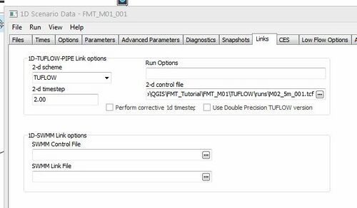
- Add the 'Links' tab by clicking View> Tabs > Links. On the 'Links' tab, enter the following parameters:
- 2-d Scheme: TUFLOW
- 2-d Timestep: 2
- 2-d control file: full path to the FMT_M01_001.tcf from the \FMT_Tutorial\FMT_M01\TUFLOW\runs folder
- Add the 'Additional Output' tab by clicking View> Tabs > Additional Output. On the 'Additional Output' tab, select the check box for '2D Flow...'. This will add extra output to check the Flood Modeller and TUFLOW link. We will review this additional output in the following section.
- Save the Scenario Data.
- Ensure that you set up the installation folders.
- Move the batch file to the FMT_Tutorial\FMT_M01\Flood_Modeller\IEF folder
- Open the batch file in a text editor. On the 'set FloodModeller=' line, change the path from the one provided to the full path to the ISISf32.exe file that you set up with the installation folders.
- Save and close the file
- Double click the batch file in your file explorer to run the file
This concludes the changes that we need to make to the .tcf
Flood Modeller Simulation Files
In the FMT_M01\Flood_Modeller folder, we have provided a complete Flood Modeller model. It is located in the DAT, IED and IEF folders.
The DAT and IED files are complete and will not require any modification to link to TUFLOW.
However, we will alter the IEF to create the link. The IEF alterations can be done either in a text editor of your choice or using the Flood Modeller Interface.
The instructions below have been written for the Flood Modeller Interface version 4.2.
IEF File


Run the Simulation
There are a number of different methods in which to start a Flood Modeller – TUFLOW model. Please refer to the following page for a detailed discussion on each of these methods.
Use your preferred method to start the model FMT_M01_001.ief or follow the guidance below. If the simulation fails to start, please refer to the troubleshooting guidance on this page.
In the Complete_Model\FMT_M01\Flood_Modeller\IEF folder a batch file has been provided. To use the batch file in this tutorial:
When the simulation is running, the Flood Modeller status window will open. Flood Modeller will then open a black TUFLOW DOS window.
File:FMT DOS window.JPG
The simulation will take a few minutes depending on the hardware setup.
Review the Results
Modelled results can be processed, reviewed and visualised in many different packages.
For a complete introduction to the different options, refer to Tutorial Module 1.